
- Catalogs
- Thomson Industries, Inc.
- Linear Actuators

Linear Actuators
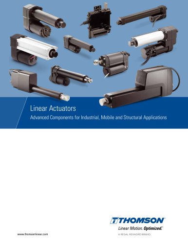
Linear Actuators
Thomson is a prominent provider of mechanical motion technology, offering a wide array of standard and custom solutions across various industries. With over 75 years of experience, Thomson delivers optimized motion solutions that balance performance, longevity, and cost.
Electric linear actuators are versatile, user-friendly, and cost-effective. They are compact, robust, operate cleanly, and require no maintenance. Modern actuators are equipped with onboard controls for improved performance and diagnostics.
Transitioning from pneumatic or hydraulic systems to electric actuators enhances controllability, reduces complexity, and minimizes the system footprint. Electric actuators are energy-efficient, environmentally friendly, and maintenance-free, leading to cost reductions.
Thomson's smart actuators feature modular control architecture and bus communication capabilities, enabling synchronized motion and enhanced control without external systems. These actuators boost efficiency, reliability, and productivity while reducing complexity and costs.
The document lists various Thomson actuator models, such as Electrak HD, MD, GX, LA14, LA24, B-Track, and H-Track, each tailored for specific applications and environments.
Thomson actuators are utilized in diverse sectors, including construction, agriculture, medical, and clean energy, enhancing efficiency and safety.
Thomson provides a comprehensive range of electric linear actuators that meet various industrial needs, emphasizing smart technology and cost-effective solutions.
- Increased efficiency and productivity.
- Fewer components and less cabling.
- Minimized complexity and easier installation.
- Reduced hardware and software costs.
- Decreased machine development time.
- Reduced overall system weight.
- Improved machine functionality and performance.
- Traditional System: Each actuator is controlled individually by the host using control boxes, switches, sensors, and position feedback devices.
- Bus Communication System: All actuators communicate with the host control over the same bus, executing commands and reporting back.
- Synchronization System: One actuator acts as the master, with others following as slaves without host communication.
- Material Handling Vehicles: Improved cabin ergonomics, precise engine throttle control, and actuator assistance in opening hoods and doors.
- Agricultural Vehicles: Ideal for hard-to-reach places, integrated electronics for complex control, and applications like sieve leveling and hood lift.
- Public Transportation: Environmentally friendly electric actuators for pantographs, door actuation, and step leveling.
- Staircase Lifts and Wheelchairs: Electric actuators for seat leveling, tilting, and rail extension.
- Utility Vehicles: Assist in reducing heavy lifting and improving safety, controlling parking brakes, steering, and throttles.
- LinearMotioneering®: An online tool for sizing and selecting linear actuators, providing technical data, 3D CAD models, and purchasing options.
- Project Library: Store and access projects online from any device.
- Custom Solutions: Option to request custom solutions if standard options do not meet requirements.
- Various models of actuators with details on screw type, manual operation, static load holding, end-of-stroke protection, overload protection, input voltages, load capacities, speed, stroke length, operating temperature, duty cycle, ingress protection, and control options.
The document provides detailed technical specifications and features of various linear actuators, focusing on the Electrak HD series. It includes performance metrics, control options, and mechanical and electrical specifications.
The document outlines specifications for different actuator models, including maximum static and dynamic loads, speed, stroke length, operating temperature limits, and ingress protection ratings. The Electrak HD series supports static loads up to 18 kN and dynamic loads up to 16 kN, with speeds up to 71 mm/s.
Various control options are available, such as analog and digital position feedback, low-level switching, programmable limit switches, and CAN bus interfaces (SAE J1939 and CANopen). The document details combinations of these options for different models.
The actuators feature ball screw types, manual override, anti-rotation, and static load holding brakes. Optional mechanical features include various front and rear adapters and alternative adapter orientations.
The actuators operate on input voltages of 12, 24, and 48 Vdc, with specific current draw values for different models and load conditions. The document specifies input voltage tolerances and cable specifications.
The document includes diagrams showing load versus speed and load versus current for different actuator models, highlighting performance variations under different conditions.
An ordering key is provided to specify model, input voltage, screw type, stroke length, and control system options, allowing customization based on application requirements.
The Electrak® MD linear actuators are designed to be reliable and maintenance-free. They feature a screw type acme and nut type lead, with no manual override but include anti-rotation. They are compliant with CE, RoHs, REACH, and ISO 13766 standards.
Various control options are available, including dynamic braking, end-of-stroke protection, overload protection, temperature monitoring, and voltage monitoring. The actuators are compatible with PWM voltage and offer multiple control options such as analog position feedback and CAN bus interfaces.
The actuators support a maximum static and dynamic load ranging from 250 N to 2000 N, with speeds varying based on load. The operating temperature ranges from -40°C to 85°C, and they have a protection class of IP67/IP69K when static and IP66 when dynamic.
Available input voltages are 12 Vdc and 24 Vdc, with specific current draw values for different models. The actuators come with standard cable lengths and specific cable diameters.
The ordering key provides a structured way to specify model, input voltage, screw type, stroke length, control system options, harness options, adapter options, and connector options.
Performance diagrams illustrate the relationship between load, speed, and current for different actuator models, highlighting the dynamic load capacity.
Detailed descriptions of various control options (XXX, XXP, EXX, EXP, LXX, LLX, LXP, LLP, CNO, COO) are provided, including their functionalities, input voltages, and current requirements. Some options include analog feedback and CAN bus interfaces for advanced control and monitoring.
The Electrak® GX DC actuators offer robust and reliable performance with acme and ball screw models. They support static loads up to 18 kN and dynamic loads up to 9 kN, with stroke lengths up to 609 mm and speeds up to 61 mm/s. They include features like overload clutch and motor thermal switch for protection.
The document provides detailed specifications and ordering information for Electrak GX and LA14 linear actuators, including their mechanical and electrical features, options, and accessories.
The Electrak GX models are available with different configurations based on input voltage (1 × 230 Vac or 3 × 400 Vac), screw type (acme or ball), and load capacity ranging from 1100 N to 9000 N. The speed varies from 10 mm/s to 61 mm/s depending on the model. The Electrak LA14 models offer input voltages of 12, 24, or 36 Vdc, with dynamic load capacities up to 6800 N and speeds up to 61 mm/s.
The document outlines the ordering key for both Electrak GX and LA14 models, detailing options for stroke length, adapter hole orientation, ingress protection rating, and additional features like potentiometer feedback and manual override.
Instructions are provided for connecting the actuators to power sources, including the use of capacitors for 115 Vac and 230 Vac models. The document also explains the wiring for actuators with potentiometer options.
Various accessories are available, including capacitor kits, mounting pin kits, and magnetic sensors. The document specifies the part numbers and dimensions for these accessories.
The actuators are designed with safety features such as overload clutches and thermal switches. They comply with CE standards and offer protection classes up to IP67 for certain components.
The document provides detailed technical specifications, features, and accessories for Thomson Linear's Electrak LA14 and LA24 linear actuators. It includes information on mounting kits, electrical connections, and performance diagrams.
- Screw Types: Available in acme or ball screw models.
- Load Capacity: Static load up to 18 kN (4000 lbf) and dynamic load up to 4.5 kN (1000 lbf).
- Stroke Length: Up to 24 inches with increments of 50 mm.
- Speed: Up to 61 mm/s (2.4 in/s).
- Protection Class: Static IP45.
- Operating Temperature: -25°C to 65°C (-15°F to 150°F).
- Safety: Overload clutch and motor auto-reset thermal switch.
- Electrical Options: Potentiometer feedback and anti-coast brake.
- Mechanical Options: Various front and rear adapters, manual override.
- Materials: Corrosion-free aluminum cover tube.
- Mounting Kits: Includes mounting pin and trunnion kits for secure attachment.
- Capacitors: Required for 230 Vac actuators, available separately.
- Magnetic Sensors: Available in normally open, normally closed, and changing contact types.
- Input Voltages: 1 × 230 Vac and 3 × 400 Vac.
- Connection Details: Specific wiring instructions for actuators with and without anti-coast brakes.
- Potentiometer Options: Provides position feedback with specific output resolutions based on stroke length.
Illustrates speed and current versus load for both acme and ball screw models, providing insights into actuator performance under different conditions.
Detailed ordering key for specifying model, stroke length, adapter positions, and additional options.
- Load Capacity: Maximum static load is 13345 N (3000 lbf), with dynamic load capacities ranging from 1335 N (300 lbf) to 12460 N (2800 lbf) depending on the model.
- Speed: Varies by model, with speeds at no load ranging from 73 mm/s (2.85 in/s) to 11 mm/s (0.45 in/s).
- Stroke Length: Minimum ordering stroke is 4 inches, and maximum is 24 inches.
- Operating Temperature: -29°C to 65°C (-20°F to 150°F).
- Protection Class: IP66/IP69K, ensuring resistance to dust and high-pressure water jets.
- Electrical Specifications: Available input voltages are 12 Vdc and 24 Vdc, with a tolerance of ±10%.
- Screw Types: Available in acme and ball screw models.
- End-of-Stroke Features: Integrated controls for position feedback, end-of-stroke limit switches, and indication outputs. Externally adjustable limit switches are optional.
- Safety Features: Includes overload clutch and motor auto-reset thermal switch.
- Diagrams illustrate the relationship between speed, current, and load for both acme and ball screw models.
- Models are identified by a combination of features including screw type, dynamic load capacity, supply voltage, nut type, stroke length, and rear adapter orientation.
- Details on connecting the actuator, including polarity changes for extending and retracting, and the use of DPDT and SPDT switches.
- End-of-stroke indication outputs are available, with a maximum current of 0.5 A.
The document provides detailed technical specifications and ordering information for B-Track and H-Track linear actuators, focusing on both AC and DC models. It includes information on electrical connections, mechanical specifications, and performance diagrams.
- Actuator Types: B-Track (acme and ball screw) and H-Track (electro-hydraulic).
- Input Voltages: B-Track AC models support 115V and 230V, while DC models support 12V, 24V, 36V, 48V, and 90V. H-Track supports 12V, 24V, and 48V.
- Load Capacities: B-Track models have varying dynamic load capacities, with maximum static loads up to 13345 N (3000 lbf).
- Stroke Lengths: Standard strokes up to 24 inches for B-Track and up to 16 inches for H-Track.
- Protection Class: IP66/IP69K for B-Track and IP67/IP69K for H-Track.
- Electrical Connections: Detailed instructions for connecting actuators to power sources, including polarity changes for extending and retracting actuators.
- Ordering Information: Includes model, version, screw type, dynamic load capacity, supply voltage, nut type, stroke length, and rear adapter orientation.
- Speed and Current Diagrams: Graphs illustrating speed and current versus load for both acme and ball screw models.
- Mechanical Features: Robust design with options for manual override and anti-rotation features.
- Contact customer support for custom stroke lengths and additional data on specific voltage models.
- Ensure compliance with CE standards and consider environmental conditions when selecting models.
The document outlines specifications for various linear actuator models, including 12 Vdc, 24 Vdc, and 48 Vdc models. It details the voltage ranges, current draw at no load and maximum load, and motor lead cross-sections for 240 W and 560 W motor models. The standard motor lead length is 10 inches (254 mm).
The document provides detailed dimensions for different actuator configurations, including retracted and total lengths based on bore sizes H1, H2, and H3. It also includes weight specifications for various actuator types and stroke lengths.
Three main load configurations are described: Configuration C (gravity resists load when extending), Configuration N (gravity does not affect load), and Configuration H (gravity assists load when extending).
The document provides guidelines for sizing bore and extension tubes based on stroke length and load requirements. It includes diagrams for determining the appropriate bore size for specific applications.
Performance matrices are provided for different models, detailing maximum dynamic loads, current draw, and speed at both extension and retraction. Electrical connections are specified, including supply voltage ranges and instructions for extending and retracting the actuator.
An ordering key is provided to specify bore size, load configuration, input voltage, motor power, pump size, extension tube diameter, front adapter type, stroke length, and rear adapter orientation.
The Electrak® 1 S model features include a compact design, integrated end-of-stroke limit switches, corrosion-resistant housing, and a self-locking acme screw drive system. It is maintenance-free and suitable for replacing pneumatic and hydraulic cylinders.
Specifications include maximum static and dynamic loads, speed at no load and maximum load, operating temperature limits, duty cycle, and protection class. Electrical specifications cover available input voltages, voltage tolerance, and current draw.
The document includes performance diagrams illustrating load versus speed and current for different actuator models and configurations.
Specifications
The Electrak 1 S and SP models are linear actuators available in 12 Vdc and 24 Vdc versions. They feature acme screw types and are designed for dynamic loads ranging from 110 N to 340 N. The models offer different maximum speeds depending on the load capacity, with the highest being 75 mm/s for the 110 N load.
The ordering key for these models includes options for CE compliance, dynamic load capacity, screw type, maximum speed, stroke length, connector options, and adapter options. The stroke lengths range from 0.82 inches to 7.82 inches for the S model and 1.2 inches to 9.2 inches for the SP model.
For the S model, the actuator extends when the yellow lead is connected to positive and the black or white lead to negative. The SP model includes a potentiometer for feedback, with specific connections for extending and retracting the actuator.
The SP model includes features such as a compact design, corrosion-resistant housing, and a self-locking acme screw drive system. It is maintenance-free and includes a 10 kOhm potentiometer for feedback.
Performance diagrams indicate speed and current versus load for both 12 Vdc and 24 Vdc models, showing variations in speed and current draw based on dynamic load capacities.
Specifications
The M-Track models are designed for dynamic loads from 111 N to 734 N, with speeds ranging from 6 mm/s to 45 mm/s depending on the load. They are available in 12 Vdc and 24 Vdc versions.
The ordering key includes model and input voltage, dynamic load capacity, screw type, stroke length, and control options. Stroke lengths range from 1 inch to 12 inches.
Connections involve a DPDT switch for extending and retracting the actuator, with specific leads for potentiometer feedback.
Specifications
Designed for office or medical applications, these models are small, quiet, and lightweight. They feature a worm screw type and are available in 12, 24, and 36 Vdc versions.
They include internal limit switches, an overload clutch, and an auto-reset thermal switch. The models are maintenance-free and have a minimum estimated life of 40,000 cycles.
The document provides detailed specifications, ordering information, and technical features for various linear actuator models, highlighting their applications, electrical connections, and performance characteristics.
The document outlines the mechanical specifications for various models of linear actuators, including Electrak® 050, Max Jac®, and Electrak® Throttle. Key parameters include maximum static and dynamic loads, speed at no load and maximum load, ordering stroke lengths, and operating temperature limits. For instance, the Electrak® 050 models have a maximum static load ranging from 280 N to 1020 N and a dynamic load from 140 N to 510 N. The Max Jac® models offer a maximum static load of up to 2000 N for worm screw types and 350 N for ball screw types.
The document provides details on input voltages, current draw, and electrical connections for the actuators. Electrak® 050 models are available in 12, 24, and 36 Vdc, while Max Jac® models are available in 12 and 24 Vdc. The Electrak® Throttle models also support 12 and 24 Vdc with specific current draw ratings.
Performance diagrams illustrate the relationship between speed, current, and load for different actuator models. These diagrams help in understanding how the actuators perform under various load conditions.
The document includes ordering keys for each actuator model, detailing options for dynamic load capacity, stroke length, and additional features like feedback options and connector types.
The actuators are designed with various protection classes, such as IP56 for Electrak® 050 and IP69K for Max Jac® and Electrak® Throttle, ensuring durability in harsh environments. Compliance with CE standards is also noted.
Optional features include digital feedback, analog position feedback, and integrated electronic options. The document also highlights the rugged construction and minimal maintenance requirements of the actuators.
The Electrak® Throttle is a linear actuator available in 12 Vdc and 24 Vdc models. It offers different configurations based on dynamic load and speed, harness orientation, temperature rating, control options, connector options, and adapter orientation. Key features include analog position feedback, end-of-stroke limit switches, and SAE J1939 CAN bus compatibility.
- Dynamic Load and Speed: Options include 45 N (10 lbf) high speed and 130 N (30 lbf) standard speed.
- Temperature Rating: Standard (-40 to +85 °C) and high temperature (-40 to +125 °C) options are available.
- Control Options: Include analog feedback, end-of-stroke limit switches, and CAN bus.
- Connector Options: Flying leads or Deutsch DTM04-6P connector.
The Electrak® PPA is a heavy-duty actuator with input voltages of 12, 24, 36, or 90 Vdc. It features a ball screw drive system, static load up to 13350 N, dynamic load up to 6670 N, and stroke lengths up to 36 inches. It includes an overload clutch and motor with a thermal switch for protection.
- Mechanical: Max static load of 13350 N, dynamic load options of 3330 N and 6670 N, and speed variations based on load.
- Electrical: Input voltage tolerance of ±10%, with current draw specifications for different models.
- Dimensions: Detailed dimensions for stroke, retracted length, and weight relationships are provided.
The DMHD actuator is a self-supporting column with high load torque capability, available in 12 or 24 Vdc. It supports static loads up to 18 kN and dynamic loads up to 16 kN, with a stroke up to 600 mm and speed up to 71 mm/s. It features onboard electronics with various optional functions and is maintenance-free.
- Mechanical: Max static load of 18 kN, dynamic load options, and speed variations based on load.
- Electrical: Input voltage tolerance and current draw specifications for different models.
The document provides detailed technical specifications and features of various linear actuators, specifically focusing on the DMD, DMA, and LM80-H models. These actuators are designed for high load torque capabilities and are suitable for various applications including domestic, office, and medical environments.
The DMD and DMA models are self-supporting columns made from extruded anodized aluminum, offering high load torque capability. They support static loads up to 18 kN and dynamic loads up to 6.8 kN for DMD and 9 kN for DMA. The LM80-H model is a rodless actuator designed for horizontal operation with a maximum load of 2000 N.
The DMD and DMA models offer stroke lengths up to 24 inches with speed variations depending on the screw type (acme or ball). The LM80-H model supports stroke lengths between 500 mm and 1500 mm. The actuators are maintenance-free and feature T-slot grooves for easy mounting.
The DMD models operate on 12 or 24 Vdc, while the DMA models use a 230 Vac input. The LM80-H model supports 12 or 24 Vdc. Each model has specific current draw requirements and input voltage tolerances.
All models include safety features such as overload clutches and thermal switches. They comply with CE standards and offer various protection classes (IP65 for DMD, IP45 for DMA, and IP44/IP33 for LM80-H).
The document includes ordering keys for selecting model types, screw types, dynamic load capacities, and stroke lengths. Accessories such as T-slot bolts are available for mounting purposes.
The document provides performance diagrams illustrating speed and current versus load for different models, aiding in the selection of the appropriate actuator based on application requirements.
- Model Variants: The document details various models of linear actuators, including DTxx-T68M, DTxx-B61M, DTxx-B62M, and DTxx-B65M, each with specific dimensions and weight characteristics.
- Dimensions and Weight: The actuators are available in different stroke lengths ranging from 500 mm to 1500 mm. The dimensions (A/B) and weight vary across models, with detailed measurements provided in both metric and imperial units.
- Performance Characteristics: The document includes performance diagrams illustrating speed and current versus load for different actuator models. Maximum permissible deflection and dynamic load capacities are also specified.
- Ordering Information: An ordering key is provided, detailing options for model and input voltage, load torque capacity, stroke length, motor orientation, motor enclosure, mounting orientation, and additional options like manual override.
- Mounting and Accessories: The actuators can be mounted using a T-slot mounting kit, which includes bolts, washers, and nuts. The document specifies that the unit must be mounted horizontally or vertically with the motor down, depending on the model.
- Electrical Connections: Details on actuator supply voltage, connector pin configuration, and instructions for extending and retracting the actuator are provided.
- Compliance and Safety Features: The actuators comply with CE standards and include safety features such as holding brakes and anti-rotation mechanisms. Optional features like spline safety function and encoder feedback are available.
- Environmental Conditions: The actuators operate within a temperature range of 0 – 40°C and have a protection class of IP44 with motor enclosure and IP33 without.
- Maintenance and Customization: The actuators are maintenance-free, and customization options are available for specific application needs.
This document provides a comprehensive glossary of terms and concepts related to linear actuators, including specifications, operational guidelines, and technical features. It is intended to assist in understanding the functionality and customization of actuators.
The document outlines various specifications such as duty cycle, dynamic load, and input voltage. The duty cycle is defined as the ratio of on-time to the total cycle time, affecting actuator performance based on load and ambient temperature. Dynamic load refers to the load an actuator can move when powered, while input voltage indicates the nominal voltage required for operation.
Key features include dynamic braking, electronic limit switches (ELS), and electronic load monitoring (ELM). Dynamic braking shortens the coasting distance of the actuator, while ELS and ELM provide safety by cutting power during overload or end-of-stroke conditions.
The document describes control mechanisms such as encoder feedback and potentiometer feedback, which help determine the position of the actuator's extension tube. Pulse Width Modulation (PWM) is also discussed as a method to control motor speed.
Various IP ratings are explained, indicating the level of protection against dust and water. The document also mentions compliance with regulations like REACH and RoHS, ensuring safety and environmental standards.
Installation instructions emphasize proper mounting to avoid binding and ensure optimal performance. Maintenance is generally minimal, with some models offering repair kits.
Other features include manual override for power failures, overload clutch for protection, and side loading considerations. The document also provides guidance on selecting the appropriate actuator based on application needs.
To ensure synchronized operation of actuators, precision is crucial to prevent binding effects. Solutions include mechanically linking non-driven actuators or using encoders with controls designed for synchronous operation, provided there is no onboard electronics preventing PWM operation. Electrak HD models with the SYN option have built-in controls for synchronized operation between multiple units of the same type.
Tension loads stretch the actuator, while compression loads compress it. Most actuators can handle both types of loads equally. For bi-directional loads, consider the end play of the actuator extension tube, especially in positioning tasks.
The document provides contact details for Thomson offices across various regions, including the USA, Canada, Mexico, Europe, Asia, and South America, with specific addresses, phone numbers, and email contacts for each location.
Catalog excerpts
Advanced Components for Industrial, Mobile and Structural Applications www.thomsonlinear.com A REGAL REXNORD BRAND
Open the catalog to page 1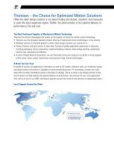
Thomson – the Choice for Optimized Motion Solutions Often the ideal design solution is not about finding the fastest, sturdiest, most accurate or even the least expensive option. Rather, the ideal solution is the optimal balance of performance, life and cost. The Best Positioned Supplier of Mechanical Motion Technology Thomson has several advantages that makes us the supplier of choice for motion control technology. • Thomson own the broadest standard product offering of mechanical motion technologies in the industry. • Modified versions of standard product or white sheet design solutions are...
Open the catalog to page 2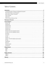
Linear Actuators
Open the catalog to page 3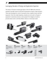
Leveraging Decades of Design and Application Expertise The history of Thomson actuators goes back to the mid-1960s when American engineers used ball screws to build the first generation of electric linear actuators. These were developed for control of accessory drives on garden tractors and farm equipment. Since that simple beginning, actuators are now used in all types of equipment to automate processes, remove people from dangerous situations, provide remote control, and make difficult, tedious or manual jobs easier. The first electric linear actuators, designed for agricultural equipment,...
Open the catalog to page 4
Linear Actuators Today, Thomson is the market leader for electric linear actuators used in the most demanding applications, including construction and agriculture vehicles. We routinely collaborate with OEMs globally to solve problems, boost efficiency and enhance the value passed on to their customers. Call us today to discuss how our vast offering of standard or custom solutions can deliver the optimal balance of performance, life and installed cost for you and your applications. Thomson actuators help people every day at home or work, during commuting, or when visiting the doctor, dentist...
Open the catalog to page 5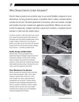
Why Choose Electric Linear Actuators? Electric linear actuators are versatile, easy to use and affordable compared to most alternatives. As long as electric power is available, there is likely a suitable electric actuator for the job. The latest generation of actuators, which are smarter, stronger and sturdier, have also created new application possibilities. Where you once had to look for expensive, complex and often custom-built solutions, a standard electric actuator is often now the simple choice. An electric actuator is often the easiest way to move from manual to powered motion since electricity...
Open the catalog to page 6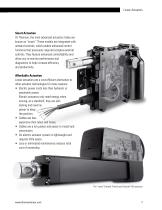
Linear Actuators Smart Actuation At Thomson, the most advanced actuators today are known as "smart." These models are integrated with onboard controls, which enable enhanced control functions that previously required complex external controls. They feature enhanced controllability and allow you to monitor performance and diagnostics to help increase efficiency and productivity. Linear actuators are a cost-efficient alternative to other actuator technologies for many reasons: • Electric power costs less than hydraulic or pneumatic power. Electric actuators only need energy when moving; at a standstill,...
Open the catalog to page 7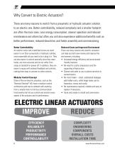
Why Convert to Electric Actuators? There are many reasons to switch from a pneumatic or hydraulic actuator solution to an electric one. Better controllability, reduced complexity and a smaller footprint are often the main ones. Less energy consumption, cleaner operation and reduced maintenance are others but often you will also experience additional benefits such as better performance, reduced downtime, and faster assembly and commissioning. Better Controllability An electric motor and a lead/ball screw are much easier to run than a pneumatic or hydraulic cylinder, since essentially all you need...
Open the catalog to page 8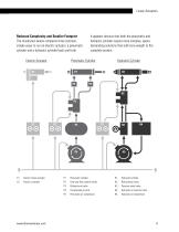
Linear Actuators The illustration below compares three common, simple ways to run an electric actuator, a pneumatic cylinder and a hydraulic cylinder back and forth. It appears obvious that both the pneumatic and hydraulic cylinder require more complex, spacedemanding solutions that add more weight to the complete system. Electric Actuator Pneumatic Cylinder Hydraulic Cylinder E1. Electric linear actuator P1. Pneumatic cylinder P2. One-way flow control valves P3. Bidirectional valve H3. Pressure relief valve H4. Hydraulic oil reservoir tank
Open the catalog to page 9
Smart Actuators As the industrial world becomes increasingly connected, the designer's need for intelligent components that can communicate with each other and operate without the need for manual interaction is growing. Thomson is meeting this demand and helping to usher in a new generation of "smart" actuators where a modular onboard control architecture and the possibility to use bus communication are key features. Smart Actuator Benefits • Increased efficiency and productivity. • Fewer components and less cabling. • Minimized complexity and easier installation. • Reduced hardware and software...
Open the catalog to page 10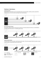
Linear Actuators Traditional vs. Smart Systems Traditional System Each actuator is controlled by the host individually. By using control boxes, switches, sensors and position feedback devices, the host controls and keeps track of each actuator. Bus Communication System All actuators speak to the host control over the same bus, and each actuator does what it is commanded to and reports back when done or if something goes wrong. Synchronization System The host control runs one actuator, which becomes the master. The other actuators follow the master as slaves without having to communicate with...
Open the catalog to page 11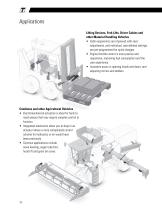
Lifting Devices, Fork Lifts, Driver Cabins and other Material Handling Vehicles • Cabin ergonomics are improved with seat adjustments, and individual, user-defined settings are pre-programmed for quick changes. • Engine throttle control is more precise and responsive, improving fuel consumption and the user experience. • Actuators assist in opening hoods and doors, and adjusting mirrors and ladders. Combines and other Agricultural Vehicles • Electromechanical actuation is ideal for hard-to-reach places that may require complex control to function. • Integrated electronics allow you to drop in...
Open the catalog to page 12All Thomson Industries, Inc. catalogs and technical brochures
 Precision Ball Splines
44 Pages
 Electrak® LL
24 Pages
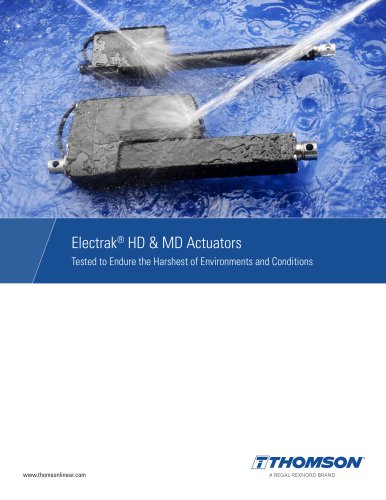 Electrak® HD & MD Actuators
8 Pages
Archived catalogs
 A12C10A5-12M0BH-DEE
3 Pages
 A12C10A5-12M0BN-DEE
3 Pages
 Electrak® HD
36 Pages
 Linear Actuators
168 Pages
 A12C10A5-10M0BN-DEE
3 Pages
 A12C05A5-06M0BH-DEE
3 Pages
 HD12B017-0100LXX2MMSD
4 Pages
 HD12B017-0100SYN2MMSD
4 Pages
 HD12B017-0150LXX2MMSD
4 Pages
 HD12B017-0250SYN2MMSD
4 Pages
 HD12B017-0250LXX2MMSD
4 Pages