- Catalogs
- Thomson Industries, Inc.
- Precision Ball Splines
Precision Ball Splines
1 /44Pages
Precision Ball Splines
1 /44Pages
Catalog excerpts

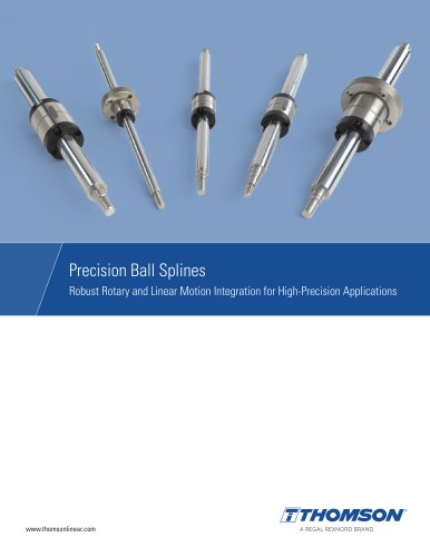
Precision Ball Splines Robust Rotary and Linear Motion Integration for High-Precision Applications
Open the catalog to page 1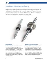
Multi-Motion Performance and Stability As automation spreads farther and wider into the industrial sector, the need for flexible solutions that address multi-axis motion exponentially grows. Thomson precision ball splines meet the demands of this trend by offering nearly frictionfree linear and rotary motion integrated on a single shaft. Merging Motions Thanks to a design that incorporates one or more linear grooves that guide balls along the shaft, Thomson precision ball splines provide a low-friction path and enable transmission of torsional loads. Their unique ability to integrate rotary and...
Open the catalog to page 2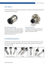
Precision Ball Splines Nut Options To best accommodate your application requirements, two different nut options are available for Thomson precision ball splines. This spline nut features a straight cylindrical shape and uses a key to mount it to the housing. While the nut includes a keyway and separate key, a matching keyway must be bored into the housing or block to that will be mounted on the nut. As this spline nut only requires a rough bore and mounting holes drilled and tapped to secure the flange, it is much easier to install. End Machining Options Depending on your shape requirements,...
Open the catalog to page 3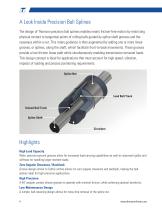
A Look Inside Precision Ball Splines The design of Thomson precision ball splines enables nearly friction-free motion by restricting physical contact to tangential points of rolling balls guided by spline shaft grooves and the raceways within a nut. This rotary guidance is then augmented by adding one or more linear grooves, or splines, along the shaft, which facilitate front-to-back movements. These grooves provide a low-friction linear path while simultaneously enabling transmission torsional loads. This design concept is ideal for applications that must account for high speed, vibration, impacts...
Open the catalog to page 4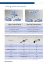
Precision Ball Splines Note: The diameter size (16 mm) is used for comparison purposes only. Thomson precision ball splines are available in diameters from 6-50 mm.
Open the catalog to page 5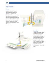
ApplicationsRobotics Faster movement and accurate positioning result in significant reductions in production time, which is critical for mass machining environments. Thomson precision ball splines simplify these systems by providing both linear and rotary motion on one shaft. Their robust capacity supplies a reliable option for tool holding in robotic applications such as CNC machining. Packaging Thomson precision ball splines simplify XYZ movement into linear and rotary motion, thereby reducing the number of parts and complexity required for picking up an item and placing it in another location....
Open the catalog to page 6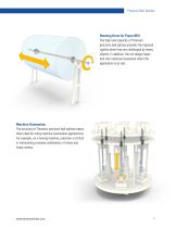
Precision Ball Splines Rotating Drum for Paper Mill The high load capacity of Thomson precision ball splines provides the required rigidity when they are challenged by heavy objects. In addition, the nut design helps lock the rotational movement when the application is at rest. Machine Automation The accuracy of Thomson precision ball splines makes them ideal for many machine automation applications. For example, on a honing machine, precision is critical in maintaining a steady combination of rotary and linear motion.
Open the catalog to page 7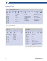
5. Accuracy Grade N = Normal 6. Spline Shaft Type 1. Spline Nut SPlA = Ball Spline Assembly 8. Number of Spline Nuts19. Nut Surface Treatment S = Standard CR = Hard Chrome SP = Black Oxide NP = Nickel Plating 10. Spline Surface Treatment S = Standard 11. Machining CTL = Cut To Length SM = Standard Machining 12. Overall Length2 Length in millimeters, example: 500.00 equals 500 mm 1. Maximum of 5 spline nuts per assembly. 2. Maximum length of 500 mm for diameters 6 and 8 mm, maximum length of 3000 mm for all other diameters. 1. Spline Nut SPLN = Ball Spline Nut 3. Nut Flange Type F = Flanged R...
Open the catalog to page 8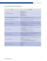
Precision Ball Splines
Open the catalog to page 9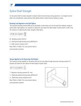
Spline Shaft Strength As the spline shaft has been designed to absorb radial load and torque during operation, its strength must be taken into consideration when precision ball splines perform under extreme loading or torque. Bending Load Applied on the Ball Spline The maximum bending moment (M) can be attributed to multi-factor such as the end fixity methods, length of spline shaft, load capacity, etc. Equation (1) helps the user obtain the ideal length of spline shaft in order to be the reference of obtaining the ideal strength of ball spline. M : Bending moment (N.mm) : Shaft permissible bending...
Open the catalog to page 10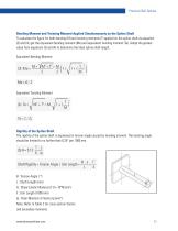
Precision Ball Splines Bending Moment and Twisting Moment Applied Simultaneously on the Spline Shaft To calculate the figure for both bending (M) and twisting moments (T) applied on the spline shaft via equation (3) and (4), get the equivalent bending moment (Me) and equivalent twisting moment (Te). Adopt the greater value from equations (3) and (4) to determine the ideal spline shaft length. Equivalent Bending Moment |3| Me = M±VMf±f= mMe = 0 Z Equivalent Twisting Moment Rigidity of the Spline Shaft The rigidity of the spline shaft is expressed in torsion angle caused by twisting moment. The...
Open the catalog to page 11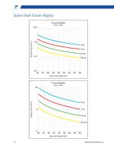
Spline Shaft Torsion Rigidity Torsion Rigidity Size = 6 mm Spine shaft length [mm] Torsion Rigidity Size = 8 mm Spine shaft length [mm] 12
Open the catalog to page 12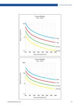
Precision Ball Splines Torsion Rigidity Size = 10 mm Spine shaft length [mm] Torsion Rigidity Size = 13 mm Spine shaft length [mm] www.thomsonlinear.com
Open the catalog to page 13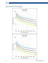
Spline Shaft Torsion Rigidity Torsion Rigidity Size = 16 mm Spine shaft length [mm] Torsion Rigidity Size = 20 mm Spine shaft length [mm] 14
Open the catalog to page 14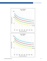
Precision Ball Splines Torsion Rigidity Size = 25 mm Spine shaft length [mm] Torsion Rigidity Size = 30 mm Spine shaft length [mm] www.thomsonlinear.com
Open the catalog to page 15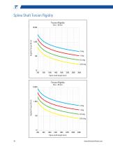
Spline Shaft Torsion Rigidity Torsion Rigidity Size = 40 mm Spine shaft length [mm] Torsion Rigidity Size = 50 mm Spine shaft length [mm] 16
Open the catalog to page 16
Precision Ball Splines
Open the catalog to page 17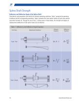
Spline Shaft Strength Deflection and Deflection Angle of the Spline Shaft Calculate by using equations that satisfy the relevant operating conditions. Table 1 presents the operating conditions and the corresponding equations. Table 2 presents the cross-section factors (Z) and cross-section secondary moments (I). Through the use of the Z, I values given in these tables, the strength and degree of displacement (deflection) of ball spline model can be obtained. Table 1 Deflection and Deflection-Angle Equation
Open the catalog to page 18All Thomson Industries, Inc. catalogs and technical brochures
 Linear Actuators
216 Pages
 Electrak® LL
24 Pages
 Electrak® HD & MD Actuators
8 Pages

Archived catalogs
 A12C10A5-12M0BH-DEE
3 Pages
 A12C10A5-12M0BN-DEE
3 Pages
 Electrak® HD
36 Pages
 Linear Actuators
168 Pages
 A12C10A5-10M0BN-DEE
3 Pages
 A12C05A5-06M0BH-DEE
3 Pages
 HD12B017-0100LXX2MMSD
4 Pages
 HD12B017-0100SYN2MMSD
4 Pages
 HD12B017-0150LXX2MMSD
4 Pages
 HD12B017-0250SYN2MMSD
4 Pages
 HD12B017-0250LXX2MMSD
4 Pages