- Catalogs
- TiMOTION Technology
- TA1 Series
TA1 Series
1 /12Pages
TA1 Series
1 /12Pages
Catalog excerpts

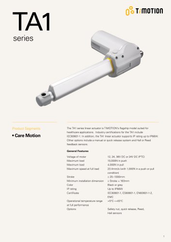
Product Segments • Care Motion The TA1 series linear actuator is TiMOTION's flagship model suited for healthcare applications. Industry certifications for the TA1 include IEC60601-1. In addition, the TA1 linear actuator supports IP rating up to IP66W. Other options include a manual or quick release system and Hall or Reed feedback sensors. General Features Voltage of motor Maximum load Maximum load Maximum speed at full load Stroke Minimum installation dimension Color IP rating Certificate Operational temperature range at full performance Options 12, 24, 36V DC or 24V DC (PTC) 10,000N in push 4,000N in pull 23.4mm/s (with 1,000N in a push or pull condition) > 25~1000mm > Stroke + 163mm Black or grey Up to IP66W IEC60601-1, ES60601-1, EN60601-1-2, EMC +5°C~+45°C Safety nut, quick release, Reed, Hall sensors
Open the catalog to page 1
Load and Speed CODE Load (N) Self Locking Force (N) Typical Current (A) No Load With Load Typical Speed (mm/s) No Load With Load Motor Speed (2600RPM, Duty Cycle 10%) C 5000 4000 Motor Speed (3400RPM, Duty Cycle 10%) L 6000 4000 Motor Speed (3800RPM, Duty Cycle 10%) Y 8000 4000 Note 1 Please refer to the approved drawing for the final authentic value. 2 This self-locking force level is reached only when a short circuit is applied on the terminals of the motor. All the TiMOTION control boxes have this feature built-in. 3 The current & speed in table are tested with 24V DC motor. With a 12V DC...
Open the catalog to page 3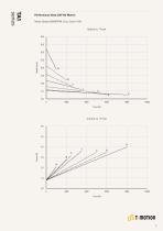
Motor Speed (2600RPM, Duty Cycle 10%) Speed vs. Thrust 40.0 35.0 30.0 Performance Data (24V DC Motor)
Open the catalog to page 4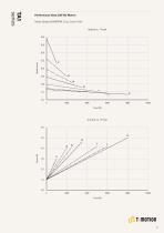
Motor Speed (3400RPM, Duty Cycle 10%) Speed vs. Thrust 40.0 35.0 30.0 Performance Data (24V DC Motor)
Open the catalog to page 5
Motor Speed (3800RPM, Duty Cycle 10%) Speed vs. Thrust 40.0 35.0 30.0 Performance Data (24V DC Motor)
Open the catalog to page 6
qo t moTion TA1 Version: 20190308-AC Voltage 1 = 12V DC 2 = 24V DC 3 = 36V DC 5 = 24V DC, PTC 0 = Plastic, U clevis, slot 8.2, depth 15.5, hole 10.2, for load push < 4000N & pull < 2500N 1 = Plastic, U clevis, slot 8.2, depth 15.5, hole 12.2, for load push < 4000N & pull < 2500N 2=Aluminum casting, U clevis, slot 8.2, depth 15.5, hole 10.2 3=Aluminum casting, U clevis, slot 8.2, depth 15.5, hole 12.2 4=Aluminum casting, U clevis, slot 10.2, depth 15.5, hole 10.2 5=Aluminum casting, U clevis, slot 10.2, depth 15.5, hole 12.2 C=Aluminum casting, U clevis, slot 8.2, depth 15.5, hole 10.2, with plastic...
Open the catalog to page 7
TA1 Ordering Key Appendix Retracted Length (mm) 2. Retracted length needs to > Stroke+Y Front Attach. C. Emergency Load (N) Release < 6000 = 6000 = 8000 = 10000 Spindle Emergency Release
Open the catalog to page 8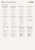
TA1 Ordering Key Appendix Rear Attachment (mm) 0 = lastic, U clevis, slot 8.2, depth P 15.5, hole 10.2, for load push < 4000N & pull < 2500N 1 = lastic, U clevis, slot 8.2, depth P 15.5, hole 12.2, for load push < 4000N & pull < 2500N 2 = luminum casting, U clevis, slot A 8.2, depth 15.5, hole 10.2 3 = luminum casting, U clevis, slot A 8.2, depth 15.5, hole 12.2 C = luminum casting, U clevis, slot A 8.2, depth 15.5, hole 10.2, with plastic T-busing 18.2 K = lastic, U clevis, slot 8.2, depth P 12.5, hole 10.2, for load push < 4000N & pull < 2500N, for spindle set hall sensors ø10.2 L = lastic,...
Open the catalog to page 9
TA1 Ordering Key Appendix Front Attachment (mm) 4 = lastic, U clevis, slot 8.2, depth P 20.2, hole 12.2, for load push < 4000N & pull < 2500N 8 = luminum casting, U clevis, slot A 6.2, depth 17.0, hole 12.2 7 = luminum casting, U clevis, slot A 6.2, depth 17.0, hole 10.2 6 = unched hole on inner tube, P without slot, hole 12.2 5 = unched hole on inner tube, P without slot, hole 10.2, with plastic bushing K = luminum CNC, without slot, A hole 10, for small backlash 10 L = luminum CNC, without slot, hole A 12, for small backlash J = luminum casting, without slot, A hole 10.2, for dental chair 9...
Open the catalog to page 10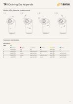
TA1 Ordering Key AppendixDirection of Rear Attachment (Counterclockwise) 1 = 0° 2 = 45° 3 = 90° 4 = 135° Functions for Limit Switches Wire Definitions CODE Pin 1 (Green) 2 (Red) O 3 (White) 4 (Black) 5 (Yellow) A (Blue) 1 extend (VDC+) N/A N/A N/A retract (VDC+) N/A 2 extend (VDC+) N/A middle switch pin B middle switch pin A retract (VDC+) N/A 3 extend (VDC+) common upper limit switch N/A retract (VDC+) lower limit switch 4 extend (VDC+) common upper limit switch medium limit switch retract (VDC+) lower limit switch 5 extend (VDC+) N/A upper limit switch common retract (VDC+) lower limit switch...
Open the catalog to page 11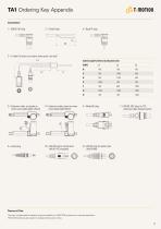
C = Y cable (For direct cut system, water proof, anti pull) Cable Length for Direct Cut System (mm) CODE LI L2 L3 D = Extension cable, not preset on R = Extension cable, preset on motor motor cover (Cable legth 120mm) cover (Cable legth 50mm) F = DIN 6P, 180° plug, for TEC extension cable standard option M = DIN 4P, plug for dental chair (40510-143, standard) N = DIN 4P, plug for dental chair (40510-040) Terms of Use The user is responsible for determining the suitability of TiMOTION products for a specific application. TiMOTION products are subject to change without prior notice.
Open the catalog to page 12All TiMOTION Technology catalogs and technical brochures
 ERGO MOTION
48 Pages
 CARE MOTION
32 Pages
 series TL3
12 Pages
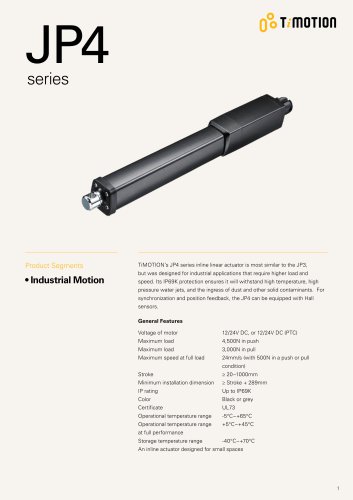 JP4 series
7 Pages
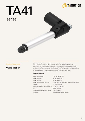 TA41 series
11 Pages
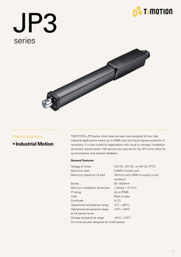 JP3 series
7 Pages
 TA6 Series
10 Pages
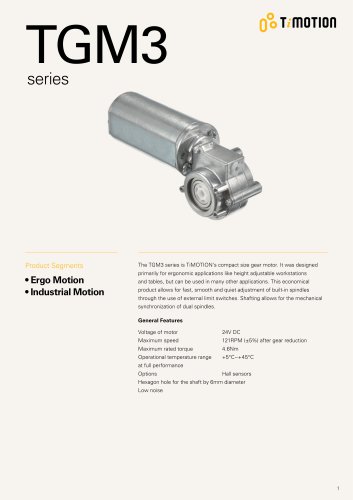 TGM3 Series
6 Pages
 TGM2 Series
7 Pages
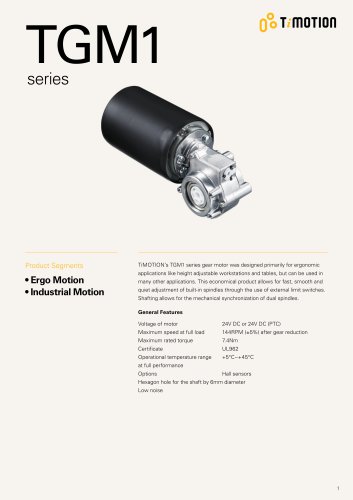 TGM1 series
7 Pages
- Electric actuator
- Medical actuator
- Lifting column
- Remote control
- Medical lifting column
- Hospital bed actuator
- Telescopic lifting column
- Gear-motor
- Cable actuator
- Medical industry gear-motor
- Bed remote control
- Hospital bed remote control
- Wireless remote control
- Patient lift actuator
- DC gear-motor
- Piston actuator
- 3-stage lifting column
- 2-stage lifting column