

- Products
- Catalogs
- News & Trends
- Exhibitions
TL3
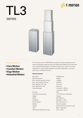
TL3
- Maximum load capacity: 4,000N (push)
- Self-locking force: 4,000N
- Maximum dynamic bending moment: 1,000Nm
- Maximum static bending moment: 2,000Nm
- Maximum speed at maximum load: 13.7mm/s
- Maximum speed at no load: 45.5mm/s
- Retracted length: ≥ Stroke/2 + 150mm or ≥ Stroke/2 + 220mm
- IP rating: IPX6
- Outer tube dimensions: 177.4*150.7mm (rectangular)
- Stages: 3-stage
- Stroke range: 250~1200mm
- Certificates: IEC60601-1, EMC
- Output signals: POT, Hall sensor * 2
- Voltage options: 12V DC; 24V DC (thermal control)
- Color options: Black, matte silver
- Operational temperature range: +5°C~+45°C
- Care Motion
- Comfort Motion
- Ergo Motion
- Industrial Motion
- The TL3 is designed for push applications and is not suitable for pull applications.
- Different retracted lengths are relative to different bending moments.
- Users are responsible for determining the suitability of TiMOTION products for specific applications.
Catalog excerpts
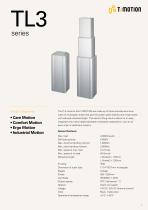
• Care Motion • Comfort Motion • Ergo Motion • Industrial Motion The TL3 columns from TiMOTION are made up of three extruded aluminum tubes of rectangular shape that give the system great stability and a high stroke with reduced retracted length. This electric lifting column allows for an easy integration into many height adjustable workstation applications, such as an exam chair in healthcare industry. General Features Max. load Self-locking force Max. dynamic bending moment Max. static bending moment Max. speed at max. load Max. speed at no load Retracted length Dimension of outer tube Output signals Operational temperature range 4,000N (push) Black, matte silver
Open the catalog to page 1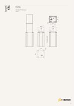
Standard Dimensions Retracted Length
Open the catalog to page 2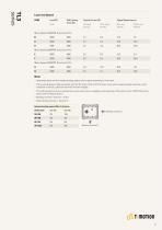
Load(N) Push Self Locking Force (N) No Load With Load No Load With Load Motor Speed (2200RPM, Duty Cycle 10%) Motor Speed (2800RPM, Duty Cycle 10%) Motor Speed (3800RPM, Duty Cycle 10%) 1 Parameters above are from tested average, please refer to approval drawing for final value. 2 The current & speed in table are tested with 24V DC motor. With a 12V DC motor, the current is approximately twice the current measured in 24V DC; speed will be similar for both voltages. 3 This self-locking force level is reached only when a short circuit is applied on the terminals of the motor. All the TiMOTION control...
Open the catalog to page 3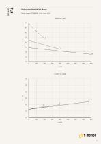
Performance Data (24V DC Motor) Motor Speed (2200RPM, Duty cycle 10%)
Open the catalog to page 4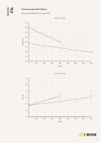
Performance Data (24V DC Motor) Motor Speed (2800RPM, Duty cycle 10%)
Open the catalog to page 5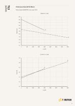
Performance Data (24V DC Motor) Motor Speed (3800RPM, Duty cycle 10%)
Open the catalog to page 6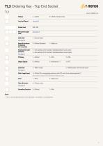
Voltage 1 = 12V DC 5 = 24V DC, thermal control Load and Speed See page 3 Retracted Length (mm) See page 10 Cable Exit See page 10 Special Functions for Spindle Sub-assembly Functions for Limit Switches See page 11 0 = Without (Standard) 1 = Safety nut 1 = Two switches at full retracted / extended positions to cut current 3 = Two switches at full retracted / extended positions to send signal Output Signals Cable Length (mm) 0 = Without 2 = Hall sensors * 2 3 = POT 2 = DIN 6P, socket, with Anti-pull buckle Color 0 = Without (The corresponding extension cable TEC needs to be ordered separately*)...
Open the catalog to page 7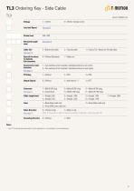
Voltage 1 = 12V DC 5 = 24V DC, thermal control Load and Speed See page 3 Retracted Length (mm) See page 10 Cable Exit See page 10 Special Functions for Spindle Sub-assembly 2 = Bottom side cable 3 = Top side cable 4 = Top (to TC) + Bottom (to TH) side cable 0 = Without (Standard) 1 = Safety nut 1 = Two switches at full retracted / extended positions to cut current 3 = Two switches at full retracted / extended positions to send signal Output Signals 0 = Without 2 = Hall sensors * 2 3 = POT Color Tubes Direction See page 12 1 = DIN 6P, 90° plug 3 = Molex 6P, 90° plug G = Molex 8P 90° plug 2 = Tinned...
Open the catalog to page 8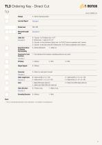
TL3 Ordering Key - Direct CutTL3 Voltage 5 = 24V DC, thermal protector Cable Exit B = Top side - for TH; Bottom side - for TP See page 10 C = Bottom side - Y cable, for TH + TP D = Top side - for the 2nd column; Bottom side - for TH & TP; direct cut operation with 2 columns E = Top side - for the 2nd column & TH; Bottom side - for TP; direct cut operation with 2 columns Special Functions 0 = Without (Standard) 1 = Safety nut Functions for Limit 1 = Two switches at full retracted / extended positions to cut current Connector C = Direct cut, water proof, anti-pull Cable Length (mm) B = Cable exit...
Open the catalog to page 9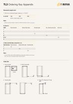
TL3 Ordering Key Appendix Retracted Length (mm) 1 Different retracted length is relative to different bending moment, See page 3. CODE Top End Socket Bottom Side Cable Top Side Cable Top + Bottom side cable Direct Cut C. When with POT (When without POT, C = 0) Cable Exit Code Top End Socket Bottom Side Cable Top Side Cable 1 If met S>700mm & RL=S/2+150 & Bottom side cable conditions at the same time, the minimum retracted length needs to+20mm. Cable Exit 4 = Top (to TC) + Bottom (to TH) side cable [
Open the catalog to page 10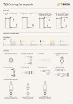
TL3 Ordering Key AppendixCable Exit B = Top side - for TH; Bottom side for TP C = Bottom side - Y cable, for TH + TP D = Top side - for the 2nd column; Bottom side - for TH & TP; direct cut operation with 2 columns E = Top side - for the 2nd column & TH; Bottom side - for TP; direct cut operation with 2 columns Functions for Limit Switches Wire Definitions CODE Pin • 1 (Green) 2 (Red) O 3 (White) 4 (Black) 5 (Yellow) A (Blue) 1 extend (VDC+) N/A N/A N/A retract (VDC+) N/A 3 extend (VDC+) common upper limit switch N/A retract (VDC+) lower limit switch 1 = DIN 6P, socket (Top end socket) 1 = DIN...
Open the catalog to page 11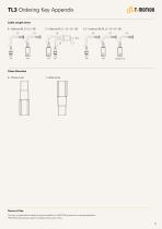
TL3 Ordering Key Appendix Cable Length (mm) B = Cable exit #B, L2 = L3 = 100 L2 Tubes Direction 0 = Thinner on top Terms of Use The user is responsible for determining the suitability of TiMOTION products for a specific application. TiMOTION products are subject to change without prior notice.
Open the catalog to page 12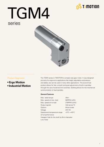
Archived catalogs
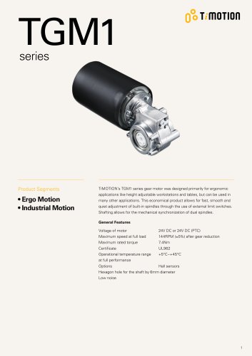 TGM1 series
7 Pages
 TGM2 Series
7 Pages
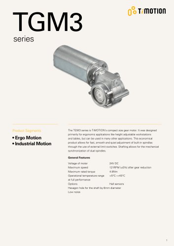 TGM3 Series
6 Pages
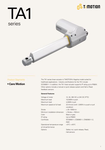 TA1 Series
12 Pages
 TA6 Series
10 Pages
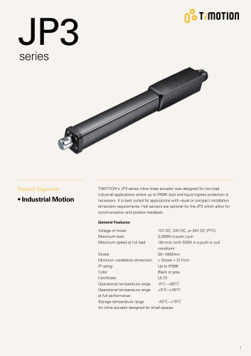 JP3 series
7 Pages
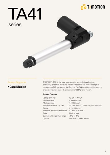 TA41 series
11 Pages
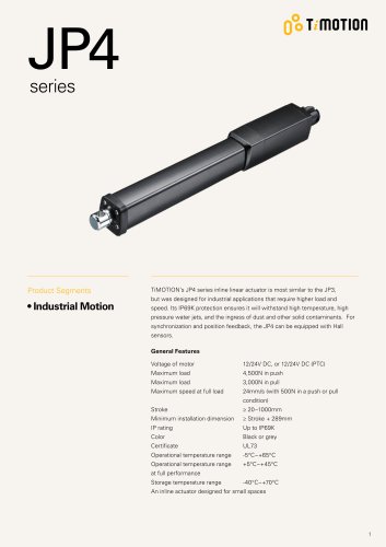 JP4 series
7 Pages
 series TL3
12 Pages
 CARE MOTION
32 Pages
 ERGO MOTION
48 Pages
- Actuator
- Linear actuator
- Electric actuator
- Medical device battery
- Medical actuator
- Compact battery
- Remote control
- Medical lifting column
- Hospital bed actuator
- Gear-motor
- Telescopic lifting column
- Medical industry gear-motor
- Cable actuator
- Bed remote control
- Wireless remote control
- Hospital bed remote control
- Patient lift actuator
- DC gear-motor
- Piston actuator