Refa
1 /80Pages

Refa
1 /80Pages
Catalog excerpts

Refa Technical Specifications
Open the catalog to page 1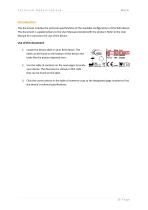
Technical Specifications Introduction This document includes the technical specifications of the available configurations of the Refa device. This document is supplementary to the User Manual provided with the product. Refer to the User Manual for instructions for use of the device. Use of this document 1. Locate the device label on your Refa device. The label can be found on the bottom of the device and looks like the picture depicted here: 2. Use the table of contents on the next pages to locate your device. The document is sorted on REF code that can be found on the label. 3. Click the correct...
Open the catalog to page 2
Technical Specifications
Open the catalog to page 3
Technical Specifications
Open the catalog to page 4
Technical Specifications
Open the catalog to page 5
Technical Specifications Headcap connector This table describes the relation between signal channel numbers and headcap connector pin numbers.
Open the catalog to page 6
Technical Specifications
Open the catalog to page 7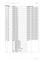
Technical Specifications Channel list:
Open the catalog to page 8
Technical Specifications Headcap connector This table describes the relation between signal channel numbers and headcap connector pin numbers.
Open the catalog to page 9
Technical Specifications
Open the catalog to page 10
Technical Specifications Channel list:
Open the catalog to page 11
Technical Specifications Headcap connector This table describes the relation between signal channel numbers and headcap connector pin numbers.
Open the catalog to page 12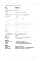
Technical Specifications
Open the catalog to page 13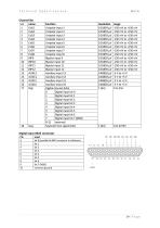
Technical Specifications Channel list:
Open the catalog to page 14
Technical Specifications RMS Noise Gain Input signal difference Input common mode range Input impedance CMRR Connectors
Open the catalog to page 15
Technical Specifications Channel list:
Open the catalog to page 16
Technical Specifications Headcap connector This table describes the relation between signal channel numbers and headcap connector pin numbers.
Open the catalog to page 17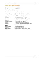
Technical Specifications RMS Noise Gain Input signal difference Input common mode range Input impedance CMRR Connectors
Open the catalog to page 18
Technical Specifications Channel list:
Open the catalog to page 19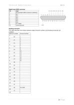
Technical Specifications Headcap connector This table describes the relation between signal channel numbers and headcap connector pin numbers.
Open the catalog to page 20
Technical Specifications Unipolar ExG inputs (EEG, ECG, EOG, EMG etc): RMS Noise < 1 pV (@ lowest sample frequency) Input signal difference -150 mV to +150 mV (@ 0 V common signal) Input common mode range -2 V to +2 V (@ 0 V differential signal) Input impedance > 100 MQ active shielded micro coax per channel subD37 female unshielded per 32 channels Digital input Input turn-on current Isolation Connector 2 mA @ 3 V input, max. input = 5 V > 4000 V, by means of optocoupler (H11L1) 8 bit via DB25 female, shared first bit via BNC female Sampling: Number of channels Resolution Sample...
Open the catalog to page 21
Technical Specifications Channel list:
Open the catalog to page 22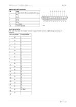
Technical Specifications Headcap connector This table describes the relation between signal channel numbers and headcap connector pin numbers.
Open the catalog to page 23
Technical Specifications Unipolar ExG inputs (EEG, ECG, EOG, EMG etc): RMS Noise < 1 pV (@ lowest sample frequency) Input signal difference -150 mV to +150 mV (@ 0 V common signal) Input common mode range -2 V to +2 V (@ 0 V differential signal) Input impedance > 100 MQ active shielded micro coax per channel subD37 female unshielded per 32 channels Digital input Input turn-on current Isolation Connector 2 mA @ 3 V input, max. input = 5 V > 4000 V, by means of optocoupler (H11L1) 8 bit via DB25 female, shared first bit via BNC female Sampling: Number of channels Resolution Sample...
Open the catalog to page 24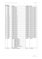
Technical Specifications Channel list:
Open the catalog to page 25
Technical Specifications Headcap connector This table describes the relation between signal channel numbers and headcap connector pin numbers.
Open the catalog to page 26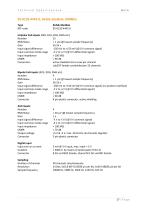
Technical Specifications
Open the catalog to page 27
Technical Specifications
Open the catalog to page 28
Technical Specifications Headcap connector This table describes the relation between signal channel numbers and headcap connector pin numbers.
Open the catalog to page 29
Technical Specifications
Open the catalog to page 30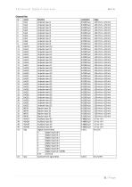
Technical Specifications
Open the catalog to page 31
Technical Specifications Headcap connector This table describes the relation between signal channel numbers and headcap connector pin numbers.
Open the catalog to page 32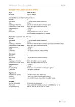
Technical Specifications
Open the catalog to page 33
Technical Specifications
Open the catalog to page 34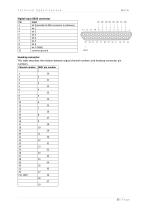
Technical Specifications Headcap connector This table describes the relation between signal channel numbers and headcap connector pin numbers.
Open the catalog to page 35
Technical Specifications
Open the catalog to page 36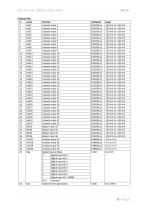
Technical Specifications
Open the catalog to page 37
Technical Specifications Headcap connector This table describes the relation between signal channel numbers and headcap connector pin numbers.
Open the catalog to page 38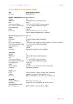
Technical Specifications
Open the catalog to page 39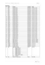
Technical Specifications
Open the catalog to page 40
Technical Specifications Headcap connector This table describes the relation between signal channel numbers and headcap connector pin numbers.
Open the catalog to page 41
Technical Specifications
Open the catalog to page 42
Technical Specifications Channel list:
Open the catalog to page 43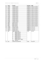
Technical Specifications
Open the catalog to page 44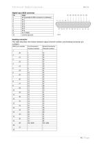
Technical Specifications Headcap connector This table describes the relation between signal channel numbers and headcap connector pin numbers.
Open the catalog to page 45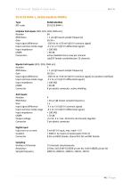
Technical Specifications
Open the catalog to page 46
Technical Specifications Channel list:
Open the catalog to page 47
Technical Specifications
Open the catalog to page 48
Technical Specifications Headcap connector This table describes the relation between signal channel numbers and headcap connector pin numbers.
Open the catalog to page 49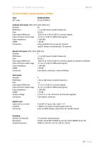
Technical Specifications
Open the catalog to page 50
Technical Specifications Channel list:
Open the catalog to page 51
Technical Specifications
Open the catalog to page 52
Technical Specifications Headcap connector This table describes the relation between signal channel numbers and headcap connector pin numbers.
Open the catalog to page 53
Technical Specifications
Open the catalog to page 54
Technical Specifications Channel list:
Open the catalog to page 55
Technical Specifications
Open the catalog to page 56
Technical Specifications Headcap connector This table describes the relation between signal channel numbers and headcap connector pin numbers.
Open the catalog to page 57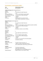
Technical Specifications
Open the catalog to page 58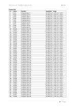
Technical Specifications Channel list:
Open the catalog to page 59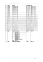
Technical Specifications
Open the catalog to page 60
Technical Specifications Headcap connector This table describes the relation between signal channel numbers and headcap connector pin numbers.
Open the catalog to page 61
Technical Specifications
Open the catalog to page 62
Technical Specifications Channel list:
Open the catalog to page 63
Technical Specifications
Open the catalog to page 64
Technical Specifications Headcap connector This table describes the relation between signal channel numbers and headcap connector pin numbers.
Open the catalog to page 65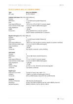
Technical Specifications
Open the catalog to page 66
Technical Specifications
Open the catalog to page 67
Technical Specifications Headcap connector This table describes the relation between signal channel numbers and headcap connector pin numbers.
Open the catalog to page 70All TMSi systems catalogs and technical brochures
 Measuring respiration
13 Pages
 Mobi
Mobi16 Pages
 Porti 7
153 Pages

- Analysis software
- Visualization software
- ECG cable
- Straight electrode
- Monitoring sensor
- Acquisition software
- Electrophysiological exploration electrode
- Import software
- Sharing software
- EMG electrode
- Medical web application
- Electrophysiology amplifier
- EEG electrophysiology amplifier
- 32-channel electrophysiology amplifier
- EMG electrophysiology amplifier
- Electrophysiology software
- 64-channel electrophysiology amplifier
- Tablet PC web application
- Cutaneous electrode
- Windows web application