Monitor QA

Monitor QA
TOTOKU has developed the "i model" to enhance quality management in medical diagnostic displays. This model incorporates a built-in luminance sensor to manage luminance and gamma, essential for image quality, and works with TOTOKU's "PM Medivisor" software to automate quality management, reducing time and cost for PACS administrators.
Luminance and Gamma Relationship: Luminance and gamma are critical in medical imaging quality. Gamma refers to the output luminance characteristics versus input values, as defined by GSDF in DICOM standards. Changes in luminance can disrupt gamma settings, impacting image diagnosis.
Causes of Luminance Changes: Luminance changes can occur due to backlight degradation or optical component wear, as fluorescent lamps and optical materials degrade over time.
The "i model" employs a built-in front sensor for precise luminance stabilization, featuring a feedback loop with a luminance sensor and control circuit. This technology offers better stability than backlight sensor technology, enabling real-time monitoring and gamma quality control.
Built-in Front Sensor: The fixed sensor avoids mechanical failures and noise, providing real-time luminance monitoring and is designed to be small and shielded from ambient light.
Luminance Stabilization System: The system is optimized with a correction table to manage center luminance effectively, with regular calibration using an external sensor to ensure accuracy.
The "i model" features an advanced luminance control system, correcting luminance several times per second and stabilizing quickly. It reduces the time to reach target luminance to under one minute, compared to 60 minutes without control. Users can monitor luminance via On Screen Display (OSD) or "PM Medivisor" software, which tracks luminance across networked displays and alerts administrators if luminance cannot be maintained.
The "i model" simplifies the evaluation of gamma characteristics to ensure compliance with DICOM GSDF standards, using AAPM TG18 guidelines. This involves 18 luminance measurements and calculations of contrast and luminance response values. Compliance is determined by comparing these values to DICOM GSDF standards, with a threshold of 10% deviation. The "i model" automates this complex test, allowing users to continue diagnostics without interruption.
The "i model" offers a robust solution for maintaining image quality in medical displays through advanced luminance stabilization and gamma management. It addresses challenges posed by luminance changes, ensuring consistent diagnostic accuracy, and reduces workload for system administrators, especially in large PACS installations. Key benefits include comprehensive luminance control, automatic calibration updates, and centralized management of DICOM conformance and calibration data through "PM Medivisor".
Catalog excerpts
TOTOKU White Paper Monitor QA Management "i model Flat Display Systems for Medical Imaging
Open the catalog to page 1
Monitor QA Management “i model” Table of Contents 1. Preface ------------------------------------------------------------------------------------------------------- 3 2. Changes in Image Quality ------------------------------------------------------------------------------- 3 2-1 Relationship between luminance and gamma ----------------------------------------------- 3 2-2 Causes of luminance changes ------------------------------------------------------------------- 5 2-2-1 Light source ---------------------------------------------------------------------------------- 5 2-2-2 Optical components...
Open the catalog to page 2
TOTOKU White Paper Together with the growing prevalence of PACS and the increasing awareness of medical diagnostic display quality management, guidelines and international standards are being developed around the world. Simultaneously, the healthcare industry has become more aware of the necessity to implement a simple and quantitative quality management on a daily basis in order to keep up with the increasing number of medical displays installed on site. In response to this demand, TOTOKU has brought the "i model" into the market. The i model is equipped with a luminance sensor situated in the...
Open the catalog to page 3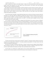
GSDF as defined here is based on the "Barten Model", a model of the visual characteristics of human eyes, which enables visually linear grayscales at the entire range of low to high luminance. The concept of JND (Just Noticeable Difference) is useful to understand the mechanism. JND is defined as the minimum amount of change in luminance necessary for human to perceive. As shown in Figure 1, the required change in luminance for human perception is less in lower levels of luminance, but the change is greater in higher levels of luminance. Human eyes are more sensitive to brightness changes in...
Open the catalog to page 4
TOTOKU White Paper 2-2 Causes of luminance changes We discussed how luminance changes affect gamma and described why luminance must be stabilized. Now let us consider what causes a variance in luminance. The possible causes are mainly described as follows: A change in brightness of the backlight light source components A change in the reflectivity over time and transmittance of optical We will look into each factor for variation in the following section. Light Source Glass Sheet Alignment layer - Fluorescent Lamp Backlight system Figure 3 LCD panel cross section Fluorescent lamps are commonly...
Open the catalog to page 5
3. Solution Presented by “i model” This section describes how the “i model” resolves the problems caused by the factors affecting luminance to enable high precision in luminance stabilization, and furthermore explains how luminance and gamma accuracy are managed. A commonly used luminance stabilization mechanism consists of a light control circuit, a luminance sensor, and a feedback system. It becomes apparent that the properties of the installed sensor, its location, and the accuracy of the light control circuit all can affect the degree of stabilization. In developing the “i model”, after carefully...
Open the catalog to page 6
TOTOKU White Paper Table 1. Sensor Types Comparison 3-2 Luminance stabilization system Let us now explain the structure of the built-in front sensor technology of the "i model". Figure 5 shows the diagram of the luminance stabilization system with built-in front sensor. Measured Date Built-in Sensor Correction Table Gamma Correction Lookup Table Power Source Driver Circuitry External Luminance Sensor •During Normal Operation Figure 5. Diagram of i model's built-in front sensor In order to achieve high level of luminance stabilization, the system is highly optimized in different levels such as...
Open the catalog to page 7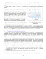
TOTOKU White Paper The correction table is created upon regular calibration with an external luminance sensor attached to the center of the The data obtained will be used as a reference of the luminance control circuit, which is updated with every external The luminance stabilization is operated whenever the display is on. Luminance variation from the target value (maximum luminance) is continuously corrected several tens of times per second at the beginning and several times per second after luminance stabilizes. This is because the rate of variation is higher for a certain time after start-up....
Open the catalog to page 8
4 The luminance response value δ, or contrast for a JND in each measurement range, is calculated. δi = 2(L’'I-L’'I-1)/(L’'I+L’'I-1)(JI-1-JI) 5 The above steps 1) - 4) are performed for the target DICOM GSDF, and the target luminance response value δid is calculated. 6 The difference of the luminance response between DICOM GSDF and measured data is calculated. κδ= Max(|δi-δid|) 7 For diagnosis applications, this value is considered to be in compliance with DICOM GSDF if it is less than 10%; if it is more than 10%, it is considered as out of compliance. The luminance response value δ calculated...
Open the catalog to page 9
TOTOKU White Paper ENGINEERING GROUP Copyright© 2007 Totoku Electric Co., Ltd. All rights reserved.
Open the catalog to page 10All TOTOKU catalogs and technical brochures
 CCL220 CCL244
2 Pages
 ccl196
2 Pages
 CCL 650i2
2 Pages
 ME195
ME1952 Pages
 ME205
ME2052 Pages
 CCL550i2
2 Pages
 Whiscut (Suspension Wire)
2 Pages
 CCL 650 i 2
2 Pages


