- Catalogs
- True Phantom Solutions
- User Manual TO-A03
- Company
- Products
- Catalogs
- News & Trends
- Exhibitions
User Manual TO-A03
1 /23Pages
User Manual TO-A03
1 /23Pages
Catalog excerpts
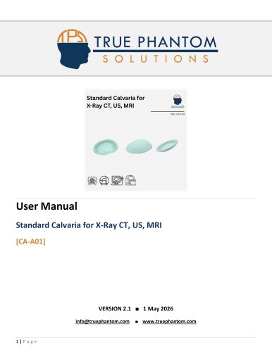
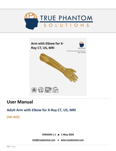
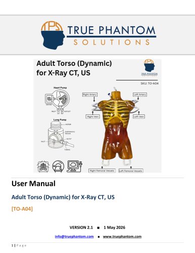
TRUE PHANTOMSOLUTIONSAdult Torso (Cardiac) IBUE PHANIOM Heart Pump Right Femoral Vessels | |left Femoral Vessels Adult Torso (Cardiac) for X-Ray CT, MRI[TO-A03] VERSION 2.9 ■ 1 May 2026
Open the catalog to page 1
TRUE PHANTOM SOLUTIONS INC.
Open the catalog to page 2
TRUE PHANTOM SOLUTIONS INC. Description Adult Human Torso (Cardiac) with a beating heart is a lifelike phantom/simulator, anatomically realistic, from neck to pelvic area with all the essential organs present inside. This phantom can be made compatible with XRay/CT and MRI. It is an ideal tool for conducting medical research under the guidance of medical imaging. The organs, bones, and body tissue mimics closely that of an adult human body. In terms of MRI applications, the phantom tissues have realistic T2 relaxation time values which makes this product to be best fit for any T2-weighted MRI...
Open the catalog to page 3
TRUE PHANTOM SOLUTIONS INC. TO-A03 | User Manual Complete Spine Complete Ribcage Shoulders and Clavicles Pelvis Partial Femoral Bones Trachea Realistic Heart with: - Right Ventricle - Moderator Band that runs from the anterior wall to the septum bridge - Left Ventricle - Papillary muscles to the anterior and posterior walls - Right Atrium - Right atrial appendage with distinct muscle structures - Left Atrium - Unique muscle structure to the appendage of the left atrium - Volume: 29 ml Appendage Feature Aorta Jugular vessels Pulmonic and Pulmonary Veins attached to LA Flexible Valvular Structures...
Open the catalog to page 4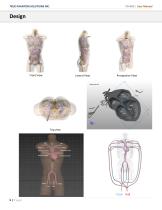
TRUE PHANTOM SOLUTIONS INC. Front View Lateral View Perspective View
Open the catalog to page 5
TRUE PHANTOM SOLUTIONS INC. Components Included Adult Torso Variable Displacement Heart Pump with Speed Controller (Optional) Primary Tubes for Connecting Pump to Heart Tubing
Open the catalog to page 6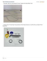
TRUE PHANTOM SOLUTIONS INC. Secondary Tubes for Connecting the Primary Tubing to the Heart/Water Tank Thread Locker, Thread Tape, Pump Lubricants, Piston Ring Compressor, Hex Wrenches, and Spare Piston Rings/Seals
Open the catalog to page 7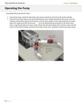
TRUE PHANTOM SOLUTIONS INC. Operating the Pump Assembling the pump with the heart Using thread tape, attach the Wye Split check valve assembly to the front of the pump chamber. Connect the primary tubes to the pump following the color coding indicated by the zip ties. The red indicates arterial flow (away from the heart), and the blue indicates venous flow (towards the heart). Attach the single tube with the blue zip tie to the barbed fitting connected to the white check valve, using the included worm gear clamp. Attach the branched tubing with 2 diverter valves and red zip ties to the barbed...
Open the catalog to page 8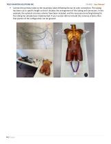
TRUE PHANTOM SOLUTIONS INC. Connect the primary tubes to the secondary tubes following the zip tie color convention. The tubing has been cut to specific length so that it dictates the arrangement of the tubing and connectors. In this example, the optional coronary arteries have been included, and the necessary branching/valving for the tubing has already been implemented. If your version did not include the coronary arteries then that portion of the configuration can be ignored.
Open the catalog to page 9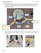
TRUE PHANTOM SOLUTIONS INC. System Operating Using a large, filled reservoir (~10L or more) insert the 2 exposed end of the primary tubes connected to the pump and diverter valves. Set the diverter valves to the below configuration. Where the valves attached to the open-ended tubes are open, and the first branch of the diverter is open, but the connecting valve is closed. OPEN OPEN Pump Heart/Water Tank Side Ensure that all ball vales, the ones closest to the pump, and the one connected to the coronary arteries (if applicable) are open as well. Valve position indicates flow, in line with...
Open the catalog to page 10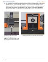
TRUE PHANTOM SOLUTIONS INC. With the reservoir full and the valves set according to the manual. If the pump has not been used in a while the piston can become stuck to the cylinder wall and require more torque than the motor is capable of breaking it free. In which case it is recommended that the piston be manually actuated via the handwheel attached to the rotating assembly to free the piston and provide a small degree of lubrication to the cylinder walls. Once this is completed, then the pump can be turned on, and the speed slowly increases. Handwheel used to break piston free/used during adjustment...
Open the catalog to page 11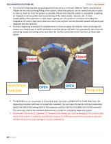
TRUE PHANTOM SOLUTIONS INC. It is recommended that the pump displacement be set to a minimum 100ml or higher, and speed of 70bpm for the initial priming/filling of the system. Allow the pump to run for several minutes in order to clear as much air from the system as possible. Please note that the system is susceptible to getting air trapped at various points due to positioning of the tubes, pump, reservoir, etc. It is the responsibility of the operator to raise, lower, agitate, etc. the system in a manner that allow the trapped air to reach a high point close to a return line so that it can be...
Open the catalog to page 12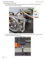
TRUE PHANTOM SOLUTIONS INC. Adjusting the Pump Displacement The pump has 4 pre-set achievable volume displacements; 65ml, 110ml, 155ml, and 200ml (from closest to the center of rotation, outwards). To access the rotating assembly, the shield must first be removed. Using a 5/32” hex key, remove the shield from around the rotating assembly.
Open the catalog to page 13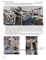
TRUE PHANTOM SOLUTIONS INC. Using a #2 Phillips and 3/16 hex key, loosen the bolt and barrel assembly, and remove the bolt. Slide the barrel out as much as possible and move the rod end out of the way. Using a 1/8” hex key, loosen the set screw on the support bearing attached to the acrylic block. Loosen the set screws on the bottom of the indexable crank adapters with a 3/32” hex key. Remove the crank adapters fully and insert the threaded barrel into the appropriate position (this step is only necessary when utilizing the low displacement settings where the barrel cannot be removed from the...
Open the catalog to page 14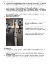
TRUE PHANTOM SOLUTIONS INC. With the barrel inserted at the right displacement value, replace the crank adapters to their designated position in the pump, install the rod end back onto the barrel and loosely assemble the rotating assembly in place. Using the handwheel, rotate the assembly to where the crank adapter and the rod end are in maximum contact with another so we can begin the alignment phase. While the pump has a versatile U-joint capable of compensating for misalignment, it is best for the longevity and function of the pump that it be aligned as much as possible. Move the positioning...
Open the catalog to page 15All True Phantom Solutions catalogs and technical brochures
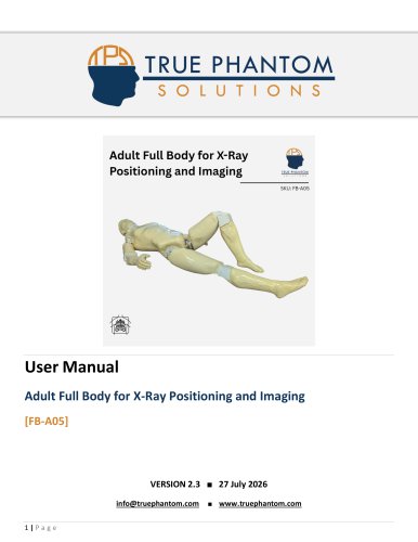 User Manual FB-A05
12 Pages
 User Manual FB-P01
12 Pages
 User Manual FB-A02
12 Pages
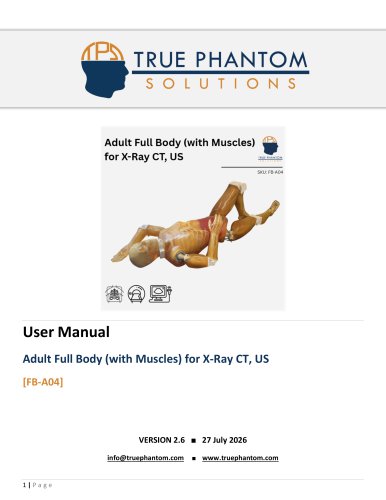 User Manual FB-A04
12 Pages
 User Manual US-A04
8 Pages
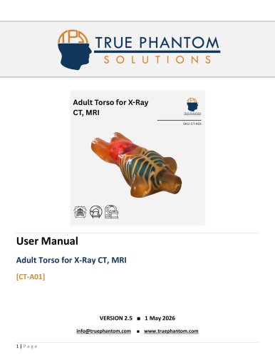 User Manual CT-A01
10 Pages
 User Manual RT-C04
7 Pages
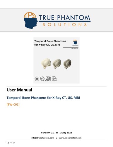 User Manual TW-C01
7 Pages
 User Manual CA-C01
7 Pages
 User Manual SL-A03
7 Pages
 User Manual HN-P01
9 Pages
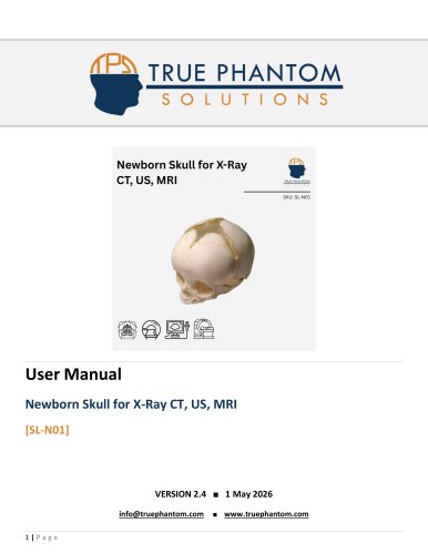 User Manual SL-N01
8 Pages
 User Manual HD-N02
8 Pages
 User Manual HD-N03
8 Pages
 User Manual HD-N01
8 Pages
 User Manual AM-S01
8 Pages
 User Manual HD-QC1
8 Pages
 User Manual DP-C01
8 Pages
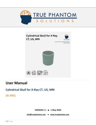 User Manual SL-G01
8 Pages
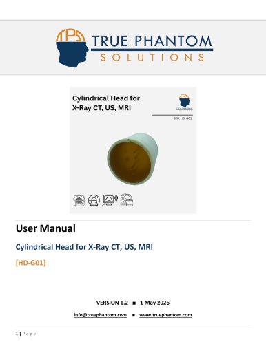 User Manual HD-G01
8 Pages
 User Manual TX-A01
8 Pages
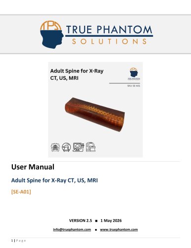 User Manual SE-A01
8 Pages
 User Manual SL-A02
8 Pages
 User Manual SL-A01
8 Pages
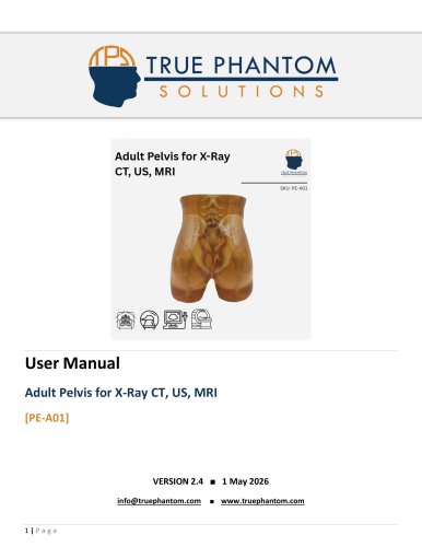 User Manual PE-A01
8 Pages
 User Manual LG-A01
8 Pages
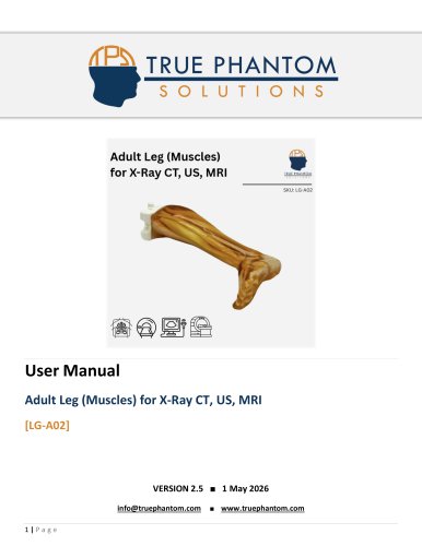 User Manual LG-A02
8 Pages
 User Manual KE-A01
8 Pages
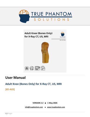 User Manual KE-A03
8 Pages
 User Manual HT-A02
8 Pages
 User Manual HT-A01
9 Pages
 User Manual HD-A04
8 Pages
 User Manual HD-A03
10 Pages
 User Manual HD-A01
8 Pages
 User Manual HD-C02
9 Pages
 User Manual HD-A05
8 Pages
 User Manual HD-C03
10 Pages
 User Manual HD-A02
8 Pages
 User Manual FT-A01
8 Pages
 User Manual AR-E01
8 Pages
 User Manual ER-A01
8 Pages
 User Manual BT-A01
8 Pages
 User Manual BT-A02
8 Pages
 User Manual BN-A02
9 Pages
 User Manual BN-A01
9 Pages
 User Manual BN-A03
7 Pages
 User Manual AR-A03
8 Pages
 User Manual AR-A01
8 Pages
 User Manual AR-A02
8 Pages
 User Manual RT-C03
7 Pages
 User Manual RT-A02
7 Pages
 User Manual FB-P02
11 Pages
 Assembly Instructions FB-P02
8 Pages
 User Manual US-A02
8 Pages
 User Manual US-N02
8 Pages
 User Manual AN-N01
8 Pages
 User Manual US-A02
10 Pages
 User Manual US-S01
10 Pages
 User Manual TO-A04
17 Pages
 User Manual TO-A02
16 Pages
 User Manual US-A03
9 Pages
 User Manual PE-A03
8 Pages
 User Manual KE-A02
8 Pages
 User Manual FB-A03
11 Pages
 Assembly Instructions FB-A03
9 Pages
 User Manual US-A05
12 Pages
 User Manual RT-C01
7 Pages
 User Manual RT-A01
7 Pages
 User Manual AN-N02
8 Pages
 User Manual TO-A05
18 Pages
 User Manual FB-S01
12 Pages
 Assembly Instructions FB-A01
9 Pages
 User Manual CT-A02
12 Pages
 User Manual PE-A02
8 Pages
 User Manual RT-C02
7 Pages
 User Manual SE-A03
8 Pages
 User Manual HD-D01
7 Pages
 User Manual CN-A02
11 Pages
 User Manual FB-A01
10 Pages
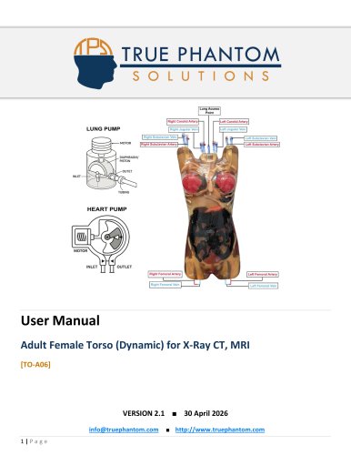 User Manual TO-A06
17 Pages
 User Manual CN-A01
8 Pages
 All Product Catalog
105 Pages
 User Manual LP-A01
6 Pages
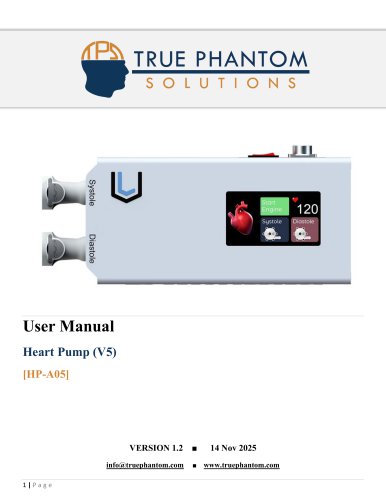 User Manual HP-A05
11 Pages
 Full Body Flyer
1 Page
Archived catalogs
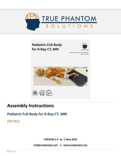 Assembly Instruction FB-P01
8 Pages
 Assembly Instructions FB-A02
9 Pages
 Assembly Instructions FB-A04
9 Pages
- Test phantom
- Tomography test phantom
- Liquid pump
- Radiography test phantom
- CT scan test phantom
- General purpose test phantom
- Ultrasound imaging test phantom
- Torso test phantom
- MRI test phantom
- Head test phantom
- Radiation therapy test phantom
- Breast test phantom
- Adjustable-flow pump
- Medical simulation pump
- Pediatric test phantom
- Piston pump
- Abdomen test phantom
- Pelvis test phantom
- Whole body test phantom
- Skull test phantom