
- Catalogs
- TST Othopedics
- humerus InSafeLOCK Nail

humerus InSafeLOCK Nail
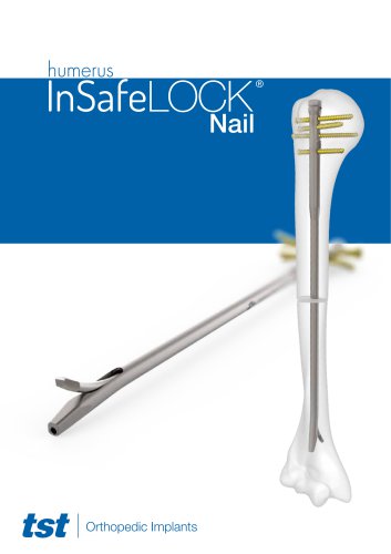
humerus InSafeLOCK Nail
The InSafeLOCK Humerus Nail is an advanced intramedullary nailing system designed for treating humerus fractures, offering a minimally invasive alternative to traditional methods. Made of biocompatible titanium, it is suitable for both right and left humerus fractures and does not require fluoroscopy for locking.
Features
The nail is available in diameters of 7 mm, 8 mm, and 9 mm, with lengths from 180 mm to 300 mm. It has a 9 mm proximal diameter and an 8 cm proximal part length, with a 5° anteriorly angled distal tip for enhanced stability. An oval-shaped hole for endopin insertion minimizes soft tissue damage.
Indications
Indicated for various humerus fractures, tumor resections, shortening osteotomies, and deformity corrections. Contraindicated in cases of infections, allergies to implant materials, and excessively contaminated open fractures.
Surgical Technique
The procedure involves digital measurement of the humerus, patient positioning, incision, and nail insertion using a guide wire. The technique supports both carved and unreamed approaches.
Locking Mechanism
Proximal locking is achieved through four screw holes at different angles, while distal locking is performed internally without incision, reducing surgery time and preventing nerve injury.
Compression Technique
Compression is achieved using various screws and shafts, allowing up to 6 mm of compression. Care is needed to avoid excessive force.
Removal Process
Involves reversing the placement procedure, detaching the end cap, and extracting the nail.
Set Detail
Includes a list of implant codes and descriptions for various nail sizes and components.
Specifications
Lists different sizes and types of Humerus Insafelock Nails, Insafelock Endopin Screws, and Cortex Screws.
Components and Accessories
Details additional components such as design trays, flexible reamers, screwdrivers, and drill bits, each with specific codes and barcodes.
Procedures and Usage
Implies use in orthopedic surgeries for humerus fractures, with sample cases suggesting practical applications.
Recommendations and Best Practices
Emphasizes using the correct size and type of nail and screw for each case to ensure compatibility and effectiveness.
Limitations and Notices
TST Medical Devices reserves the right to update or modify contents and products without notice, indicating a commitment to continuous improvement.
Catalog excerpts
InSafeLOCK Nail
Open the catalog to page 1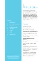
4 Features of InSafeLOCK Nail Implants Tray 1 Tray 2 Tray 3 This description is not sufficient by itself for direct and proper use of the instrument set intraoperatively. Instruction by a surgeon who is thoroughly trained and experienced in handling these instruments and in doing the procedure are highly recommended. Introduction Humerus InSafeLOCK Nail is an innovative intramedullary nailing system, developed for humerus problems. Humerus fractures have 5-6 % incidence of all bone fractures. Nowadays, conservative and surgical methods are used for the treatment of humerus fractures. Other surgical...
Open the catalog to page 2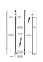
usable for both right and left Endopin (internally safe locking pin) threaded part 7,0 mm, 8,0 mm and 9,0 mm three different diameter choices 5° angled distal part to anterior special designed locking hole in the distalposterior of the nail no need to fluoroscopy for distal locking threaded endopin squeeze the posterior cortex and stuck the nail to anterior cortex posteriorly distal locking from inside to outside threaded part distally angled end, opposite locking hole on the posterior
Open the catalog to page 3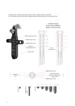
4 locking holes in the proximal, three holes are static and the other one is dynamic. 4 mm diameter locking screws allow multiple locking in different planes at the humerus head. multiple locking choices at the different angles on the proximal 0 static transverse screw angled static screw angled static screw dynamic compression screw calcar screw static transverse, dynamic compression, calcar screw angled static screw compression screw angled static screw
Open the catalog to page 4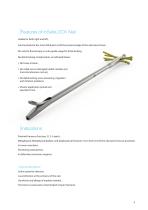
Features of InSafeLOCK Nail Usable for both right and left, Can be placed to the most distal part (until the proximal edge of the olecranon fossa), No need to fluoroscopy or extra guide usage for distal locking, No distal locking complications as indicated below; No tissue incision, No radial nerves damaged (radial, median and musculocutaneous nerves), No distal locking screw loosening, migration and irritation problems, Shorter application period and operation time. Indications Proximal humerus fractures (2, 3, 4 parts), Metaphyseal, Metaphyseal diafizer, and diaphyseal all fractures (3 cm from...
Open the catalog to page 5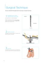
Surgical Technique Humerus InSafeLOCK Nail applied with the technique of antegrade operation DETERMINATION OF NAIL’S DIAMETER AND LENGHT ARE: a) Sturdy humerus is measured digitally. b) After measuring the humerus canal, humerus length is determined through the Surgical Ruler before the pre-operative time. PATIENT POSITION: The patient is positioned ‘supine’ or ‘sunbed’ on the table. The fracture is reducted. It is reached to humerus top in 3 cm incision from acromion to distal with the anterolateral appro
Open the catalog to page 6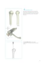
NAIL ENTRY POINT: Entering the medulla directly from the top of the head. Showed in the figure; Entry point of the nail is positioned posterolateral of biceps tendon between big tubercule and humerus head in the medial of the groove. posterior medial lateral anterior Biceps Tendon Sulcus The K-wire 3X400 mm Ø should be placed metaphyseal in the medulla canal with fluoroscopic control.
Open the catalog to page 7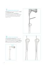
OPENING NAIL ENTRY POINT: Entry Reamer opened under the guidance of K-Wire in the Entry Reamer Sleeve. All nail diameters are 9 mm. Entry Reamer is designed for this diameter. The nail holder diameter is 11 mm and enlargement process is performed from top of the bone to 10 mm depth with the reamer (11 mm). SENDING THE GUIDE WIRE: The Long Guide Wire (Ø3X650 mm) is inserted into the intramedullary canal after opening the entry point if carving of diaphease will be done. Reduction Device can be used by fixated to T-handle in order to pass easily the fracture line and assist in reduction. guide...
Open the catalog to page 8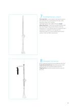
DETERMINING NAIL LENGHT: The Guide Wire is transmitted to the distal humerus, the tip of the wire is positioned at the top of the olecranon fossa, with a reamer. The length of the nail is determined by Length Measuring Device of the wire outside the bone with the aid of length measurement device. Nail size should be 6-10 mm shorter than the measured size if compression is applied in the fracture line. Otherwise, there is a risk of overflowing the bone surface of the nail after compression. UNREAMED TECHNIQUE: If the unreamed technical to be preferred; first of all Guide Wire (Ø 2X650 mm) should...
Open the catalog to page 9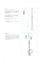
CARVED TECHNIQUE: The canal carving process is started through Guide Wire (Ø 3X650 mm) with the smallest Flexible Reamer (Ø 7 mm) and the size is continued by 0.5 mm increment. guide wire pusher While the Reamer is removing, the Guide Wire Pusher is used behind the reamer to prevent the Thick Guide Wire going back. The carving process continues until the cortex contact is felt. The nail diameter should be 1-1.5 mm smaller than the last used reamer. GUIDE-WIRE CHANGING: At the end of the canal carving process, Guide-Wire (Ø 2X650 mm) which is compatible with the inner diameter of the nail is placed...
Open the catalog to page 10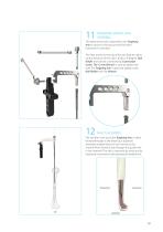
TARGETING DEVICE–NAIL ASSEMBLY The determined nail is attached to the Targeting Arm as shown in the picture and the other instrument is checked. The laser marks on the top of the nail help to matchup the direction of the nail (L (Left) or R (Right)). Nail Holder and nail are connected by Connection Screw. The 12 mm Wrench is used to tighten the bolt. The Targeting Arm is attached tightly to the Nail Holder with the Wrench. NAIL PLACEMENT: The nail that is set up to the Targeting Arm, is taken forward through as the distal tip is sloped to anteriorly straight (distal on the humerus), the channel...
Open the catalog to page 11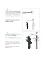
In the case of nailing needed, Connection Screw is attached to the threaded slot on the Nail Holder. Nail Hammer (inside threaded end) is tightly connected to the Connection Screw by 12 mm Wrench. Nail clamping is applied with the Sliding Hammer which is located on the Sliding Hammer Impactor. This process should be done with soft impacts which will not damage the cortex. For slight forward movements; the process should be applied by hitting the nail and screw with U Hammer through K-Wire. NAIL PROXIMAL POSITION: Nail placement could be tracked with 0, 5, 10, 15 and 20 mm nail marks on the Nail...
Open the catalog to page 12All TST Othopedics catalogs and technical brochures
 OLECRANON PLATES
1 Page
 Calcar Stem
98 Pages
 Catalog
2 Pages
 Plates&Screws Catalog
154 Pages


- Bone plate
- Compression plate
- Metallic compression plate
- Locking compression plate
- Titanium compression plate
- Distal compression plate
- Arthrodesis nail
- Table on castors
- Lateral compression plate
- External fixation system
- Metallic intramedullary nail
- Humerus compression plate
- Femoral stem
- Adult external fixation system
- Proximal fixation intramedullary nail
- Acetabular prosthesis
- Titanium intramedullary nail
- Cementless femoral stem
- Cementless acetabular prosthesis
- Tibia external fixation system