- Catalogs
- UFIT IMPLANT
- Ufit Dental Implant
Ufit Dental Implant
1 /64Pages

Ufit Dental Implant
1 /64Pages
Catalog excerpts

Dental implant Fixture & Abutment
Open the catalog to page 4
A revolution in dental implant systems SYLBUTMENT is the product of engineering research in which the perfect contact of two flat surfaces is only possible theoretically but practically impossible. Unprecedented - a remarkable sealing effect The Sealing Effect occurs because of elastic modification done by the pressure on the circular bands of the contact sides. Outstanding durability due to even stress distribution The even contact surfaces uniformly transfer power from prosthetic appliances to fixtures. Results of fatigue tests showed that not a single fatigue failure occurred when repeated...
Open the catalog to page 5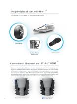
The principles of The principles of SYLBUTMENT are easily discovered around us. Tire treads Sealing effect of a piston ring Conventional Abutment and In a conventional abutment, the gap between fixture and abutment may increase gradually due to repeated chewing forces. This is due to the contact between the outer surface of the abutment and the inner taper of the fixture, which only occurs on a small surface area due to the roughness of both the two surfaces. On the other hand, SYLBUTMENT increases the contact surfaces by transformation to the grooves. It does not create a gap as the transformation...
Open the catalog to page 6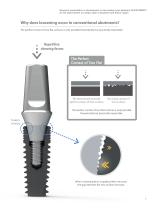
Research presentation in development of new sealing type abutment (SYLBUTMENT) for the improvement of contact state of abutment and fixture region Why does loosening occur in conventional abutments? The perfect contact of two flat surfaces is only possible theoretically but practically impossible. Repetitive chewing forces The Perfect Contact of Two Flat The theoretically possible perfect contact of two surfaces The actual contact of two surfaces The perfect contact of two flat surfaces is only possible theoretically but practically impossible. When a chewing force is applied then removed, the...
Open the catalog to page 7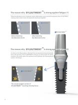
When the abutment screw is fastened, elastic deformation occurs around the grooves of the SYLBUTMENT, creating a force which moves the abutment and fixture together. As shown in the figure above, chewing forces are experienced asymmetrically due to the grooves of the SYLBUTMENT acting as an elastic body. This firmly maintains the sealed state of the abutment and distributes the chewing forces evenly in the fixture.
Open the catalog to page 8
Pressure distribution at the contact surfaces of the Fixtures and the Abutments (FEM Analysis) When conventional abutments experience asymmetrical chewing forces, the contact surfaces of the fixtures and abutments are separated; however, when a SYLBUTMENT is used, the contact surfaces are not separated. Conventional Abutment Fatigue Limit Load (Newton) Load (Newton) Conventional Abutments can withstand 5 million repeated loads of 344N~34N, but the SYLBUTMENT can withstand 5 million repeated loads of 552N~55N. Fatigue Limit Conventional Abutment
Open the catalog to page 9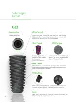
2.5 Hex indentation and 11 degree Morse Taper. 2.5 Hex Micro Thread The deep 0.2 mm micro thread increases the surface area and induces a smooth connection with the larger main thread. Additionally, the micro thread increases thread contact with bone thereby improving the initial fixation effect. Dual Thread RBM Surface Surface areas are increased through blasting by highly biocompatible Calcium-Phosphate Media. As 0.8mm pitch of dual thread type, the surgery time is reduced. (1.6mm per 1 rotation) Main Thread When the fixture is inserted into the implant bed, the conical shape and lower deep...
Open the catalog to page 10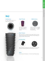
Dual Thread As 0.8 Dual Thread Type, the placing speed is very fast. (1.6mm per 1 rotation) Connection 2.5 Hex fastening Type of 11 degree Morse Taper Type Surface areas are increased through blasting by highly biocompatible Calcium-Phosphate Media. Main Thread When the fixture is inserted into the implant bed, the conical shape and lower deep thread of the fixture increase stability and make immediate loading possible. When placing the implants, the cutting edge of the Twist Type increases Self Tapping ability and minimizes Bone resistance. As a structure of D (Diameter) - 0.7mm, the overall...
Open the catalog to page 11
Submerged system Flow chart Solid impression coping Solid abutment Cover screw Healing abutment
Open the catalog to page 12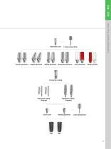
Angled abutment Submerged System Flow Chart Abutment screw Milling abutment Temporary abutment UCLA abutment Plastic cylinder Impression coping (Pick-up) Impression coping (Transfer) Cover screw Healing abutment
Open the catalog to page 13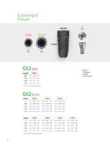
• Mini Regular Wide • Ultra-wide
Open the catalog to page 14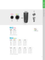
* Use mini size abutment • Mini Regular Wide • Ultra-wide
Open the catalog to page 15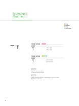
• Mini Regular Wide • Ultra-wide Cover screw Iminij Height 0.5 MICS 5005 Cover screw Height 0.5 2 Use 1.2 Hex hand driver 5~8Ncm Joining torque Used to prevent foreign materials from entering after the fixture insertion
Open the catalog to page 16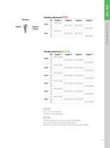
Height Gingiva GH Height 3 Height 4 Height 5 Height 7 Healing abutment GH Height 3 Height 4 Height 5 Height 7 Use 1.2 Hex hand driver 5~8Ncm of joining torque Used to protect the connecting part of the implant Acts as the shape of the gingiva after surgery Abutment is chosen according to the patien's gingival height.
Open the catalog to page 17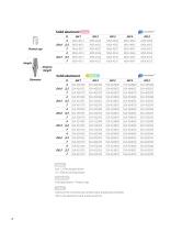
mini ISYLBUTMENT -LGingiva Height Solid abutment Br/W/U ^Isylbutment Use 1.2 Hex torque driver 25~35Ncm joining torque Solid abutment + Protect cap Used on the conventional cement type produced prosthesis All-in-one abutment and screw structure
Open the catalog to page 18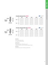
Transfer abutment Hex ^mmi ^Isylbutment™ H GH1 GH 2 GH 3 GH 4 GH 5 Use 1.2 Hex torque driver 25~35Ncm joining torque Transfer abutment + Abutment screw Choice of variety of sizes according to gingival height Conventional cement retained type abutment
Open the catalog to page 19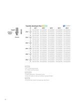
Use 1.2 Hex torque driver 25~35Ncm joining torque Transfer abutment + Abutment screw Choice of variety of sizes according to gingival height Conventional cement retained type abutment
Open the catalog to page 20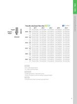
Transfer abutment Non-Hex R/W/U Gingiva Height Use 1.2 Hex torque driver 25~35Ncm joining torque Transfer abutment + Abutment screw Choice of variety of sizes according to gingival height Conventional cement retained type abutment
Open the catalog to page 21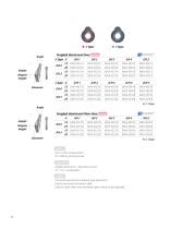
Angled abutment Hex ^mrni ^ Isylbutment™ AType A GH1 GH2 GH3 GH 4 GH 5 Use 1.2 Hex torque driver 25~35Ncm joining torque Angled abutment + Abutment screw 15° / 25° composition Conventional cement retained type abutment Used in revising the fixture's path Used in cases when the prosthesis' path needs to be adjusted
Open the catalog to page 22All UFIT IMPLANT catalogs and technical brochures
 dental implant system
54 Pages

- Implant abutment
- Titanium implant abutment
- Straight implant abutment
- Dental surgery instrument kit
- Titanium dental implant
- Internal implant abutment
- Conical dental implant
- Angled implant abutment
- Drill bit
- Dental implant surgery instrument kit
- Hexagonal implant abutment
- Screw implant abutment
- Dental implant analog
- Straight dental implant analog
- Hexagonal dental implant
- Dental drill bit
- Internal hexagon dental implant