
Catalog excerpts

Lubinus SP II Anatomically Adapted Cemented Hip System Surgical Technique
Open the catalog to page 1
Explanation of Pictograms Manufacturer Item number Material number Product fullfills the esseitial requirements of the Medical Device Directive 93/42/EEC
Open the catalog to page 2
Lubinus SP II Anatomically Adapted Cemented Hip System Surgical Technique 02 Preoperative Planning 05 Surgical Approaches 06 Surgical Technique Implants 12 SP II Prosthesis Stems 14 SP II Prosthesis Stems XL with long neck Instruments 16 Instruments for SP II Prosthesis Stems, Overview 17 Instrument Tray 18 Set of Rasp Stems Additional Instruments 19 Handle for Rasp Stems - Coupling of the rasp 19 Coloured Plastic Trial Heads 20 Femoral Reamers Accessories 26 Instructions for Cleaning and Maintenance 26 X-ray Templates 27 Literature 28 Indications/Contraindications Important Information
Open the catalog to page 3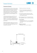
Surgical Technique Preoperative Planning Preoperative planning is conducive towards optimal surgical outcomes by ensuring the most appropriate implants are selected for the patient. The key objectives involved are the correct positioning of the central rotational point of the hip, correct leg length and finally preservation or restoration of sufficient soft tissue tension by avoiding medialisation of the femur. Achieving anatomically appropriate CCD or neck angle and head-neck length are of paramount importance. The Lubinus SP II System offers CCD angles 117°, 126° and 135° and femoral...
Open the catalog to page 4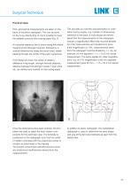
Surgical Technique Practical steps First, geometrical measurements are taken on the basis of the pelvic radiograph. This can be done on the X-ray directly (Fig. 2), but it is better to trace the skeletal contours onto tracing paper (Fig. 3). A horizontal reference line is drawn along the inferior margins of the obturator foramen, followed by a vertical reference line along the sacral crest, ideally passing through the center of the pubic symphysis. From these two lines, the center of rotation, difference in leg length, left/right femoral distance, distance between the left/right muscle T...
Open the catalog to page 5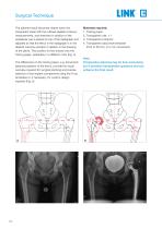
Surgical Technique The planned result becomes clearer when the transparent sheet with the outlined skeletal contours, measurements, and sketched-in position of the acetabular cup is placed on top of the radiograph and adjusted so that the femur in the radiograph is in the desired outcome position in relation to the drawing of the pelvis. This position is then traced onto the tracing paper, preferably in a different color (Fig. 4). The differences on the tracing paper, e.g. actual and planned positions of the femur, provide the visual over iew required for surgical planning and precise v...
Open the catalog to page 6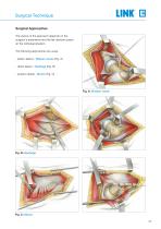
Surgical Technique Surgical Approaches The choice of the approach depends on the surgeon‘s experience and his/her decision based on the individual situation. The following approaches are usual: - antero-lateral - Watson Jones (Fig. A) - direct lateral - Hardinge (Fig. B) - postero-lateral - Moore (Fig. C)
Open the catalog to page 7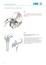
Surgical Technique The following illustrations show a posterior approach. Fig. 1 The hip is dislocated in the usual way. The standard osteotomy plane is normally at 45° to the axis of the femoral stem. Fig. 2 Resection of the femoral head according to preoperative planning. A comparison between bone situation and Resection Guide helps to decide on the resection level. Sparing resection is advisable to allow for additional resection or reaming using the calcar reamer if necessary. The resection angle is perpendicular to the axis of the femoral neck.
Open the catalog to page 8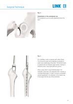
Surgical Technique Fig. 3 Implantation of the acetabular cup The acetabular cup is usually prepared before the stem. Fig. 4 The medullary cavity is opened with a Box Chisel. This should be done as far laterally as possible to avoid varus positioning of the stem. The femoral canal is opened with the Femoral Canal Opener, having it‘s entrance point in the fossa piriformis groove. When using a SP II Long Prosthesis Stem the medullary canal has to be prepared with a reamer of corresponding length. In order to ensure a consistant cement application, the diameter of the reamer has to be larger...
Open the catalog to page 9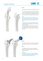
Surgical Technique Fig. 5 The Rasp Stem is inserted with coupled Rasp Handle. Due to the anatomical form of the rasps the anteversion usually adjusts itself automatically when they are driven in. The femoral canal is prepared with rasps of increasing size until the planned size is reached. Note: In order to widen the proximal lateral part the rasp can be run up and down a couple of times. Thus giving more space for the cement in this area. The size of the rasp corresponds roughly with the implants (Rasp has an oversize of 0,75 mm comparing to the Implant). In order to create a cement mantle...
Open the catalog to page 10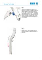
Surgical Technique Fig. 8 Trial reduction is carried out with the final size of rasp in situ. The handle is removed and the Trial Neck Segment selected in preoperative planning (right/ left, CCD angle), is placed on the rasp. The different Trial Heads are then used to check for optimal offset and correct leg length and to test whether stability is adequate. The range of movement is also checked to avoid impingement of bone and implant and rule out any instability. Fig. 9 After trial reduction, the Trial Head and Neck are removed by hand and the rasp is removed with the rasp handle.
Open the catalog to page 11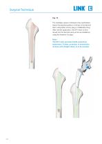
Surgical Technique Fig. 10 The medullary space is blocked a few centimeters below the planned position of the tip of the femoral stem using either a bone plug or a Medullary Plug. After cement application, the SP II stem is introduced into the femoral cavity as far as possible by using the Insertion Forceps. Note! The SP II stem provides inbuilt anatomical antetorsion. Further correction of anteversion, as done with straight stems, is to be avoided.
Open the catalog to page 12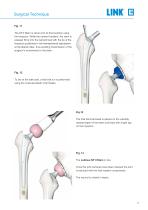
Surgical Technique Fig. 11 The SP II Stem is driven into its final position using the Impactor. While the cement hardens, the stem is pressed firmly into the cement bed with the tip of the Impactor positioned in the hemispherical depression at the lateral collar, thus avoiding transmission of the surgeon’s movements to the stem. Fig. 12 To be on the safe side, a final trial run is performed using the coloured plastic Trial Heads. Fig.13 The final Femoral Head is placed on the carefully cleaned taper of the stem and fixed with a light tap on the impactor. Fig. 14 The Lubinus SP II Stem in...
Open the catalog to page 13All Waldemar Link catalogs and technical brochures
-
 LINK Lubinus SP II
2 Pages


