DP-314

DP-314
The DP-314 is a 4-channel differential amplifier designed for amplifying signals such as EEG, EKG, and extracellular action potentials. It offers gain selections of x10, x100, x1000, and x10,000, with input impedance typically at 1012 Ω and input leakage at 1 pA. The unit features high-pass and low-pass filters, a DC operation mode, and an input-offset control. It is powered by AC line power with a voltage range of 90-120 and 220-250 V AC at 50 or 60 Hz.
Nomenclature
This section explains the text conventions used in the manual, such as bold type for product numbers and small caps for specific controls.
Control Description
The front panel includes a test circuit, input offset, high-pass and low-pass filters, gain control, and output BNCs for each channel. The rear panel houses the power cord attachment, fuse, and line voltage selector switch.
Setup and Test
Setup involves connecting the amplifier to power and the data acquisition system. A test procedure is outlined to verify the DP-314's functionality, involving setting controls, connecting to an oscilloscope, and using the test jacks.
Operation
The amplifier can operate in AC or DC mode, with configurations for differential or single-ended readings. AC mode uses capacitive coupling to block DC, while DC mode uses direct coupling for constant potential differences.
Appendix
Specifications: Includes voltage gain, input and output resistance, common-mode rejection, noise levels, and filter settings.
Warranty: Covers defects in materials and workmanship for one year, excluding damage from abuse or electrical stress.
Service: Contact information for technical support and service inquiries is provided.
Catalog excerpts

Warner Instruments 4 Channel Differential Amplifier with Active Headstages Model DP-314 Warner Instruments 1125 Dixwell Avenue, Hamden, CT 06514 (833) 668-8632 / (800) 547-6766 - support ce
Open the catalog to page 1
The DP-314 is designed for amplifying signals such as EEG, EKG and extracellular action potentials. With gain selections of x10, x100, x1000 and x10,000, V level signals are sufficiently amplified for computer signal analysis. The input impedance is typically 1012 and the input leakage is typically 1 pA. The unit features both high pass and low pass filters, plus a DC operation mode. An input-offset control nulls potentials present at the input, which can be seen at the output in DC mode. Front panel test pins apply 1 mV pulses to the headstage input to check operation of the entire system....
Open the catalog to page 3
NOMENCLATURE Text conventions This manual refers to amplifier controls at two functional levels; specific controls and the settings of these controls. To minimize the potential for confusion, we have employed the following text conventions. Product numbers are presented using bold type. References to a specific control is specified using SMALL CAPS. References to individual control settings are specified using italic type. Special comments and warnings are presented in highlighted text. Any other formatting should be apparent from context. Since our goal is to provide clarity rather...
Open the catalog to page 4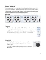
CONTROL DESCRIPTION The front panel of the DP-314 houses a TEST circuit (common to all channels), and INPUT OFFSET, HIGH PASS and LOW PASS filters, GAIN control, and OUTPUT BNC’S for each channel. The CIRCUIT and CHASSIS GROUNDS are located on the instrument rear panel along with the power cord attachment, fuse, and line voltage selector switch. Front panel Test Circuit The TEST circuit is used for evaluation of all amplifier channels and provides a 1 mV test signal for system evaluation. An LED indicates operation of the internal signal generator which is on when the small button between the...
Open the catalog to page 5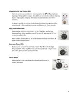
Clipping Lights and Output BNC CLIPPING LIGHTS are provided for each channel in the DP-314 and indicate clipping of the amplifier’s output. Two LEDs are provided to indicate clipping high or clipping low. Clipping offsets can be adjusted using the OFFSET CONTROL. A channel specific OUTPUT BNC is also located in this section and provides connection to a data acquisition system, oscilloscope, or chart recorder. High-pass Bessel filter Each channel as a HIGH-PASS BESSEL FILTER. This filter sets the low frequency limit of the amplifier from DC to 300 Hz in 6 steps of DC, 0.1, 1, 10, 100, and 300...
Open the catalog to page 6
Power The power section contains an LED which indicates when power is applied to the unit. Rear Panel The rear panel of the DP-314 houses the fuse/power entry module, as well as the circuit and chassis grounding jacks.
Open the catalog to page 7
SETUP AND TEST Setup Setup of the DP-314 is simple. Place the amplifier near your experiment and connect the power cable to the rear of the instrument. NOTE: Be sure the POWER SWITCH is off before connecting the amplifier to your power circuit. Run BNCs from the OUTPUT of each channel on the DP-314 to your data acquisition system. Place your headstages into position within your experimental setup and connect them to their respective channels on the amplifier. Headstages are numbered to facilitate channel assignment. Setup is complete. WARNING: DO NOT leave unused headstages connected to the amp...
Open the catalog to page 8
2. Connect the DP-314 OUTPUT BNC for the channel being tested to an oscilloscope or your data acquisition system. 3. Connect a headstage to the HEADSTAGE INPUT of each channel and turn the power on. 4. Plug the headstage for your first channel into the TEST JACKS, but not far enough to depress the TEST BUTTON between the pins. 5. Adjust the OFFSET CONTROL for a zero-volt baseline on the oscilloscope. 6. Set the HIGH-PASS FILTER control to 0.1 Hz 7. Allow time for the baseline to return to zero. 8. Push the headstage fully into the TEST JACKS (i.e.: far enough to depress the test button). NOTE:...
Open the catalog to page 9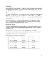
OPERATION The amplifier can be placed into either AC or DC mode, and can be used for either differential or single-ended readings. Therefore, four configurations are possible for each channel. Also, each channel can be configured independently. AC mode (per channel) In AC mode, the headstage inputs are capacitively coupled (AC coupled) to the amplifier through a DC blocking capacitor. This prevents pure DC from entering the amplifier. As a result, the amplifier output will return to baseline in the presence of a constant potential difference at the headstage inputs. The amplifier is placed in...
Open the catalog to page 10
Input Connections (per channel) The pins on the headstage represent the positive and negative inputs of a differential amplifier and the headstage case is connected to the system ground. For differential readings, use both pins for inputs. A GROUND CLIP is provided to connect the headstage case (i.e.: system ground) to the experimental ground if so desired. For single-ended readings, the GROUND CLIP can be tied to the negative input pin, allowing the positive pin to be used as the amplifier input. NOTE: The negative and positive pins are labeled on the headstage. Output Connection (per channel)...
Open the catalog to page 11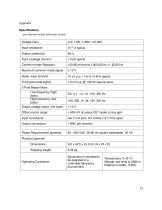
Appendix Specifications per channel unless otherwise stated Voltage Gain: Input resistance: Output resistance: Input Leakage Current: Common-mode Rejection: Maximum common-mode signal: Noise, input shorted: Front-panel test signal: 2-Pole Bessel filters Low-frequency (high pass): High-frequency (low pass): Output voltage swing (10k load): Offset control range: ± 600 mV at output (DC mode) at any gain Input connectors: two 2 mm pins, 0.5 inches (12.7 mm) apart Output connectors: Power Requirements (general): Physical (general) Dimensions Shipping weight Operating Conditions: Equipment is intended...
Open the catalog to page 12
Warranty The DP-314 is covered by our Warranty to be free from defects in materials and workmanship for a period of one year from the date of shipment. If a failure occurs within this period, we will either repair or replace the faulty component(s). This warranty does not cover failure or damage caused by physical abuse or electrical stress (e.g., inputs exceeding specified limits). In the event that repairs are necessary, shipping charges to the factory are the customer's responsibility. Return shipping will be paid by the company. Service We recommend that all questions regarding service be...
Open the catalog to page 13All Warner Instruments catalogs and technical brochures
 Warner Instruments
28 Pages
 CHARTMASTER
6 Pages
 EPC 10 USB
12 Pages
 Warner Full-line Catalog
426 Pages
- Laboratory incubator
- Benchtop laboratory incubator
- LED light source
- Digital controller
- Cell culture laboratory incubator
- Microscope light source
- Cold light source
- Temperature control system
- Laboratory control system
- Biosignal acquisition system
- Electrophysiology amplifier
- EEG electrophysiology amplifier
- Research biosignal acquisition system
- Micromanipulator
- Organ perfusion system
- Medical warmer
- Anti-vibration table
- Micro-injector
- Animal research organ perfusion system
- Veterinary electrical stimulator