
- Catalogs
- Waston medical
- Thoracic-lumbar vertebra pedicle screw H7


- Company
- Products
- Catalogs
- News & Trends
- Exhibitions
Thoracic-lumbar vertebra pedicle screw H7

Thoracic-lumbar vertebra pedicle screw H7
Waston Medical is a prominent company in China's medical industry, specializing in spinal products and adhering to the Medical Devices Directive 93/42/EEC. The company focuses on minimally invasive surgical approaches for orthopedic spine procedures.
- WALEN Anterior Cervical Plating System: Features anatomic and ultra-low profile design with a special locking mechanism and visibility window.
- NEULEN Cervical Laminoplasty System: Provides real-time lamina support and maintains spinal canal enlargement.
Includes systems like M7, S7, H7, M9-IA, and M10-IA, tailored for conditions such as scoliosis and minimally invasive procedures.
Features the APEX-T Thoracic and APEX-L Lumbar Vertebroplasty Systems, and the APEX BALLOON for vertebral body expansion.
Offers interbody fusion cages like BULLET, BANANA, WAVE, ZERO-X, and O-MAX OLIF for lumbar and cervical applications.
Details steps for patient positioning, plate selection, curvature adjustment, screw hole preparation, and screw insertion.
Includes product codes, specifications, and quantities for anterior cervical plates, vertebral screws, and revision screws.
Guidelines for hinge preparation, opening the laminoplasty, and securing the lamina with plates and screws.
Details specifications, procedures, and surgical techniques for spinal surgeries, including instrument specifications and surgical steps.
Includes instructions for screw and rod insertion, compression/distraction techniques, and final tightening procedures.
Specifications and procedural guidelines for lumbar and cervical applications, emphasizing anatomical shapes and bone graft windows.
Focuses on the ZERO-X Cervical Interbody Fusion Cage, including specifications, procedural steps, and precautions.
Advantages include large interbody graft placement, muscle preservation, and avoidance of nerve damage, with detailed surgical techniques and instrument lists.
Catalog excerpts

PRODUCT CATALOG
Open the catalog to page 1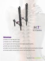
Waston Spine Waston Medical is one of the top players in China’s medical industry and together with our customers, we are driven to make healthcare be�er. Waston has collaborated with the na�on's industry-leading organiza�ons to offer a comprehensive por�olio consis�ng of tradi�onal and proprietary spinal products. Our focus on bringing progressive, compelling products to market is guided by our quality first founda�on - Waston fulfills the rigorous cer�fica�on requirements of Medical Devices Direc�ve 93/42/EEC. Our spectrum of orthopedic spine procedures is the result of Waston's responsiveness...
Open the catalog to page 2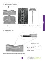
Anterior Cervical Plating System Advantage Anatomic design-the lordo�c are accod with cervical physiological structure. Ultra-low profile design-imita�on to anterior vertebral �ssues. Visibility window design-easier observa�on of gra� and the viertebral end plates. Special locking mechanism-easy opera�on, effec�vely preven�ng the screw from back out. Locking screw design-fixed & varible angle locking screw, are convenient for opera�on choice. Bending design-ensure the holes do not deform during
Open the catalog to page 4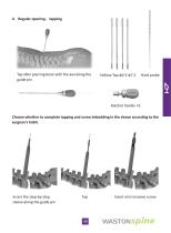
Degenera�ve disc disease Surgical technique 1. Pa�ent posi�oning and approach The pa�ent is placed in the supine posi�on with the head in slight extension. The posterior cervical spine is supported to establish and maintain normal cervical lordosis. The surgeon must then choose a right or le� sided approach to the cervical column. A�er exposing the cervical spine, the self retaining retractor is placed to provide op�mal visualiza�on. A vertebral body distractor (1507003900) may be used. The distrac�on sha�s (1507000400) are posi�oned midline in the vertebral bodies adjacent to the level to be...
Open the catalog to page 5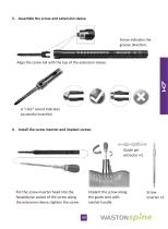
3. Adjus�ng plate curvature WALEN Anterior Cervical Plate is provided with a pre-machined lordo�c curve. If required, the plate may be contoured to increase the amount of lordo�c curvature or decrease the amount of lordo�c curvature by using the Plate Bender (1503201300). A gradual bend should be made over the en�re length of the plate and abrupt changes in curvature should be avoided. Increase Lordosis Decrease Lordosis 4. Placing temporary fixa�on pins A�er selec�ng the appropriate plate, use the Temporary Fixa�on Pins (1503201900) to hold the plate in place while drilling and placing the screws....
Open the catalog to page 6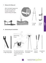
6. Drilling holes Screw angle may be selected and the plate stabilized during the drilling procedure. The Plate Holder/ Drill Guide (1503200700) may be a�ached to the plate by placing the expandable end into a lateral screw hole and turning the knurled knob clockwise. 7. Selec�ng and using drill bits The WALEN Anterior Cervical Pla�ng System offers the ability to select various angles of screw placement to conform to individual pa�ent anatomy. Some certain angles may direct the screws at vulnerable vascular and neural �ssues. Use fluoroscopy to confirm drill bit penetra�on depth and angular orienta�on...
Open the catalog to page 7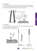
9. Inser�ng screws Select the appropriate screw length corresponding to the hole drilled. Using the Hex Driver (1503201600), pick the screw from the tray and insert it through the plate. Drill the first hole, tap if desired, and place the screw without �ghtening completely. A�er confirming proper plate posi�on, drill, tap if desired and place screw in all remaining screw holes. Begin with the lateral hole that is opposite and diagonal to the first prepared hole. Remove Temporary Fixa�on Pins and perform final �ghtening of all screws in the same sequence as men�oned above. 10. Locking the cams Locking...
Open the catalog to page 8
walen Anterior Cervical Plate (Titanium) Anterior Cervical Plate (Extended) (Titanium)
Open the catalog to page 9
1503299900 WALEN Anterior Cervical Plate Instrument Set
Open the catalog to page 10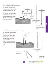
1503299900 WALEN Anterior Cervical Plate Instrument Set IJ4)
Open the catalog to page 11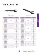
Neulen Cervical Laminoplasty System Advantage In the posterior cervical open-door opera�on, it can achieve real-�me lamina support func�on, and maximum maintain spinal canal enlarging state in laminoplasty The support piece specially designed on the underpart pf plate, can play a role of strong suppor�ng before screws be fixed, and reduce the force on screws. The plate opening is arc shaped, which can maximize accept the lamina broken end, making it more stable. The board has certain plas�city, can be fixed a�er bending according to special s
Open the catalog to page 12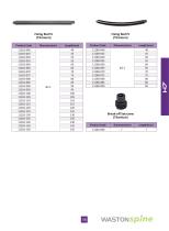
Mul�segmental OPLL Cervical spinal stenosis Mul�level cervical myelopathy Surgical technique 1. Pa�ent posi�oning The pa�ent is posi�oned prone as for most other posterior cervical procedures, with the head secured in a Mayfield three-pin head-holder, preferably in slight flexion (Figures 1 and 1a). Some cervical flexion helps reduce the overlap of the laminae and facet joints, which facilitates the laminoplasty itself. A reverse Trendelenberg posi�on may help decrease bleeding from epidural and paravertebral veins.
Open the catalog to page 13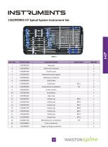
Note: In the event that the posterior decompression ought to extend to the C2 level, this can be accomplished while respec�ng the integrity of the C2 posterior arch and the majority of its muscular origins and inser�ons. A so-called dome laminectomy is performed by using a burr and kerrison to remove the lower margin of C2, followed by the cancellous bone and ventral cortex (Figures 4, 4a and 4b). 2. Surgical exposure The surgeon performs a midline posterior exposure from the inferior aspect of C2 to the superior aspect of T1 (Figures 2 and 3). The lateral dissec�on follows the subperiosteal...
Open the catalog to page 14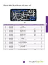
Note: The side of the spinal canal to be opened may be chosen for a number of reasons. If supplemental foraminotomies are planned, then the open side should be ipsilateral to them. If the pa�ent’s myelopathy is asymmetric, some surgeons prefer to open the more involved side. Finally, all things being equal, the choice may be influenced by the surgeon’s dominant hand. A right hand dominant surgeon will probably wish to stand on the pa�ent’s le� and open the le� side. The converse would be the case for a le�-handed surgeon. 3. Open side trough prepara�on The open side trough is prepared with a burr...
Open the catalog to page 15All Waston medical catalogs and technical brochures
 Sparkling Barbed Suture
12 Pages
 Claw Sternum Plate
4 Pages
 1201910 series
16 Pages
 Sternalink™
14 Pages
 APEX BALLOON
20 Pages
 APEX-T, APEX-L
20 Pages
 Neptuno II
8 Pages
 1500599900
2 Pages
 1500188800
2 Pages
 10603 GAMMA
2 Pages
 X Series and X series (L/R)
2 Pages
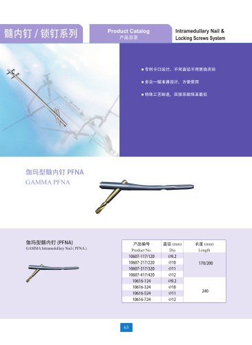
 INTRAMEDULLARY NAIL SYSTEM
9 Pages
 clavicle
5 Pages
 foot implants
24 Pages
 ulna & radius
12 Pages
 humerus
6 Pages




- WASTON bone plate
- WASTON compression plate
- WASTON metallic compression plate
- WASTON locking compression plate
- Surgery forceps
- WASTON titanium compression plate
- WASTON distal compression plate
- WASTON orthopedic surgery instrument kit
- Compression bone screw
- WASTON surgical stapler
- Sealing forceps
- WASTON disposable surgical stapler
- WASTON proximal compression plate
- Disposable forceps
- WASTON intramedullary nail
- WASTON forearm compression plate
- WASTON lateral compression plate
- Suture thread
- WASTON medial compression plate