
- Catalogs
- Waygate Technologies
- Everest Mentor Visual iQ+ : Real3DTM Measurement Handbook


Everest Mentor Visual iQ+ : Real3DTM Measurement Handbook

Everest Mentor Visual iQ+ : Real3DTM Measurement Handbook
Advancements in 3D measurement technologies have enhanced video borescopes, enabling inspectors to map, measure, and analyze in 3D. This handbook educates on the Mentor Visual iQ's measurement technologies, improving decision-making in remote visual inspections. Training is available through the Waygate Inspection Academy.
Accurate measurements in Remote Visual Inspection (RVI) prevent unnecessary downtime and costs. Traditional methods often lack data quality assessment, whereas Real3D technologies offer a 3D point cloud for better data quality and cursor placement verification.
- 3D Phase Measurement: Uses structured-light technology for accurate measurements, enhancing productivity.
- 3D Stereo Measurement: Utilizes advanced algorithms for a full 3D point cloud.
- Stereo Measurement: Traditional method using stereo images, limited by lack of a 3D point cloud.
- Comparison Measurement: Uses a physical reference target for 2D measurements.
Optimal accuracy requires clean, calibrated equipment, proper camera positioning, and suitable surface conditions. Real3D technologies can resolve feature depths to ~0.125mm with minimal errors under ideal conditions.
Different measurement types suit various applications, including length, point to line, depth, and area. Each type has specific conditions and guidelines for accuracy.
Accuracy depends on application-specific factors. A Gauge R&R study is recommended to verify accuracy requirements.
Specifications and part numbers are provided for Real3D measurement tools.
A glossary clarifies technical terms used throughout the handbook.
The Real3D Measurement system measures surfaces with minor movement, available in various probe diameters and working channels.
Consider the direction and distance from which the defect is viewed when selecting a 3DPM tip. Forward and side view tips are available with specifications for each.
Best practices include ensuring inspector qualification, using in-house procedures, and maintaining clean optics. Emphasizes tip orientation, system verification, and proper measurement setup for accuracy.
Details various measurement types, including Length, Point to Line, Depth, and more, with example applications and best practices for accuracy.
Enhance accuracy by positioning the measurement tip close to the indication and adjusting cursors for maximum green pixel coverage. Use depth map mode for better visualization.
Involves sweeping depth profile slices over an area to identify the highest or lowest point, useful for corrosion and erosion analysis.
Automatically identifies blade and liner edges to determine clearance. Use 3DPM or 3D Stereo technology based on characteristics.
Measures the angle between a reference plane and an angle plane. Position the measurement tip close to the reference surface.
Measures the area and edge lengths of a missing blade corner. Adjust cursor positions for maximum green mask coverage.
Creates a 3D circle for visual comparison against a surface shape, best used with long-range 3D Phase Measurement tips.
Extends measurement capabilities into areas with no 3D data or high noise, aiding in various measurements.
Outlines methods for using a Measurement Plane and Guide Lines to assist in measurements, emphasizing accuracy.
Includes turbine blade measurements and 3D Stitching techniques for accurate measurements.
Provides accuracy curves and discusses factors affecting accuracy, such as distance and target material composition.
Comprehensive guidelines and examples for using Measurement Planes and 3D Stitching ensure accurate measurements, particularly in turbine blade inspections.
Catalog excerpts

QWaygate _ Technologies a Baker Hughes business Real3D™ Measurement Handbook A guide to advanced 3D measurement technologies, techniques and applications for video borescopes used in remote visual inspection applications.
Open the catalog to page 1
Measurement Technologies
Open the catalog to page 2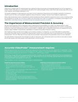
Advances in image based 3D measurement are making the video borescope an increasingly powerful tool in the inspector’s toolbox. While in the past, you could identify indications and capture images; today’s advanced video borescopes allow you to map, measure, and analyze indications in 3D. This guide is designed to help inspectors and asset owners understand measurement technologies available on the Mentor Visual iQ and how they can be properly applied to improve decision making in remote visual inspection applications. Many video borescope owners underutilize the advanced features of their inspection...
Open the catalog to page 3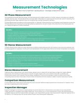
Measurement Technologies (See Mentor Visual iQ VideoProbeTM Operating Manual – Advantages of Measurement Types) Using patented structured-light technology, 3D Phase Measurement enables inspectors to locate, measure, and analyze an indication using the same tip optic. The wide field of view and large depth of field allow for measuring with the same tips used for inspecting, thus eliminating the extra steps required to back out, change the tip, and then relocate the indication. 3D Phase Measurement provides accurate measurement “on-demand” while saving time and increasing overall inspection productivity....
Open the catalog to page 4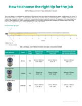
Two main things to consider when selecting a 3DPM tip are from what direction the defect is viewed and from how far away. To determine whether you need a forward view or side view tip, consider where your insertion point is in relation to the area you're inspecting. Measurement Depth of Field (DOF) values are provided as general guidelines to help select the most appropriate tip for a given application. The actual measurement DOF for a particular application depends on several factors including feature size, required accuracy, measurement types and surface finish.
Open the catalog to page 5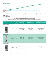
Side View Tip Specs Optical Measurement Blue, Green and Red side view tips comparison chart. Note: Green tip view is tilted up 10 degrees to improve turbine blade root visibility Color Measurement view size at max distance Part Number
Open the catalog to page 6
General Guidelines • nsure the inspector is qualified to perform measurement. E • Use in-house procedures and the selector tool on this page to choose the appropriate measurement technology and type for your application. • nsure that your measurement tip and probe optics are clean and that the tip is securely attached. If using a stereo tip, be sure to correctly E identify the tip serial number when first entering measurement. 3D Phase Measurement tips are automatically recognized by the system. • For best results when measuring on a narrow surface using 3DPM, orient the tip such that the long...
Open the catalog to page 7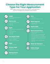
Choose the Right Measurement Type For Your Application While multiple measurement types may be used for certain applications, this chart is intended to show the expert recommendation. Length • Simple measurement of features or components Point to Line • Turbine blade edge damage • Gap width • Weld width Depth • Pits or dents from corrosion, erosion, or FOD impact • Pipe inside diameter • Weld height • Gap width Area Depth Profile • Corrosion, erosion and pitting • Maximum weld height • Maximum wear groove depth Angle • Angle on flat surfaces Surface Angle • Blade tip curl • Angle between two...
Open the catalog to page 8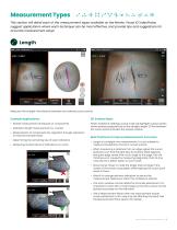
Measurement Types This section will detail each of the measurement types available on the Mentor Visual iQ VideoProbe, suggest applications where each technique can be most effective, and provide tips and suggestions for accurate measurement setup. Measures the straight-line distance between two selected cursor points. Example Applications: • Simple measurement of features or components When enabled in Settings, a blue mask will highlight surface points where planes perpendicular to the straight length 3D line between the cursor points intersect the viewed surface. • Indication length measurement...
Open the catalog to page 9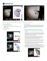
Example Applications: • Turbine blade edge damage • Estimate missing corner area using multiple point-to-line measurements • Gap or groove width • Weld width 3D Surface Mask: When enabled in Settings, a blue mask will highlight surface points where planes perpendicular to the straight 3D line between the third cursor point and the reference line intersect the viewed surface. Best Practices to Improve Measurement Accuracy: • Review the 3D point cloud to ensure your cursors are located correctly. • Space the first two cursors far apart along the reference edge. If possible, place them on opposite...
Open the catalog to page 10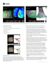
Measures the distance from a reference plane (defined by three selected points) to a fourth selected point above or below the plane. Example Applications: Best Practices to Improve Measurement Accuracy: • Blade tip to shroud gaps • he measurement tip should be as close as possible to the T indication to increase the accuracy of measurement. • Pits or dents from corrosion, erosion, or FOD impact • Pipe inside diameter • Weld height • Stator vane rock • Gap width • osition the three reference-plane cursors to maximize the P coverage of 3D Surface Mask green pixels on the reference surface. If measuring...
Open the catalog to page 11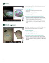
0 Multi-segment Measures a planar area on a surface by outlining an indication with multiple cursor points. Example Applications: • Missing blade corners using a Measurement Plane • Coating loss • Surface area of pitting or corrosion • FOD impact damage Best Practices to Improve Measurement Accuracy: • Check the point cloud to ensure accurate cursor placement. • When measuring a curved surface, reduce error by measuring multiple smaller areas and combining the results. • Use with a Measurement Plane to measure area and lengths of blade missing corners. See Measurement Plane section for details....
Open the catalog to page 12All Waygate Technologies catalogs and technical brochures
 VideoProbe accessories
51 Pages
 V|tome|x M Metrology 2.0
2 Pages
 Phoenix Nanotom M
8 Pages
 Phoenix X|cube series
8 Pages
 Industrial CT inspection
4 Pages
 Speed|scan HD
8 Pages
 DXR S85 Detector Upgrade
2 Pages
 Win 10 Upgrade
1 Page
 Phoenix X|aminer
8 Pages




Archived catalogs
 Phoenix V|tome|x L300
8 Pages
- Flat panel detector
- Portable flat panel detector
- Design software
- Multipurpose radiography flat panel detector
- Data management software
- AI-assisted software
- Artificial intelligence software
- HD camera
- 14 x 17 flat panel detector
- Inspection system for the pharmaceutical industry
- Automatic inspection system
- Inspection camera
- Optical inspection system
- Medical inspection system
- Camera with zoom
- Compact inspection system
- Inspection software
- X-ray inspection system
- Electronic inspection system
- Robotized inspection system