
- Catalogs
- Zimmer Biomet
- Longevity® Constrained Liner Surgical Technique


Longevity® Constrained Liner Surgical Technique

Longevity® Constrained Liner Surgical Technique
The Longevity Constrained Liner is designed for use in total hip arthroplasty (THA) to mitigate the risk of hip dislocation in patients with instability, bone loss, or tissue laxity. It is intended for patients who have exhausted other options for constrained acetabular components.
The liner is compatible with Allofit IT, Trilogy IT, and Continuum Acetabular Systems. It features cut-outs to enhance range of motion (ROM) and is made from highly crosslinked polyethylene, addressing common impingement sites.
Standard surgical techniques are used for liner removal, involving a non-self tapping screw to lift the liner without damaging the shell taper or locking mechanism.
Supplemental screws are recommended to maintain fixation at the shell-to-bone interface, especially with constrained inserts. Proper screw placement and depth measurement are crucial.
Provisional liners are available with or without a permanently affixed locking screw. Proper seating and alignment are essential, and the liner should not be impacted to avoid damage.
The trial insert assesses leg length and ROM, allowing adjustments to optimize the orientation of constraining fingers.
Before inserting the final liner, ensure the shell is clean and dry. The liner is placed by hand or with an instrument, and its position is verified before impaction. Once seated, the liner cannot be removed without damage.
The metal constraining ring is placed over the femoral component with clear engravings indicating the direction towards the femur and acetabulum. Proper assembly is crucial for successful implantation.
The assembly involves attaching a metal constraining ring to the polyethylene liner, aligned using titanium pegs and slots. Two types of ring impactors are available: Axial and Offset.
If disassembly is required, a flat instrument is used to pry the constraining ring from the liner. The liner and ring should not be reused once disassembled.
The liner is indicated for patients at high risk of hip dislocation. It is contraindicated for use with skirted femoral heads, active infections, osteoradionecrosis, and skeletal immaturity.
The product should only be used with specific acetabular shells and requires careful alignment to prevent impingement. It is for single patient use only and should not be reused.
Reported adverse effects include component loosening, failure, dislocation, infection, and metal sensitivity.
Patients should be informed about the device's limitations, including reduced ROM compared to a normal joint. Excessive loading can lead to dislocation.
The document includes item numbers and descriptions for various components and kits related to the Longevity Constrained Liner.
The document lists constrained liners by size (28mm, 32mm, and 36mm) with detailed item numbers and descriptions, including dimensions such as pole and lip measurements.
The document references a surgical technique for the Longevity Constrained Liner, emphasizing the need for individual patient examination and advice.
The document includes a disclaimer that the information is general and advises consulting package inserts for detailed product information.
The Longevity Polyethylene Liner Thickness Chart provides specific measurements for each liner size, indicating the presence of a lip and its dimensions.
The document mentions the CE mark's validity and provides contact information for Zimmer representatives and a website for further inquiries.
Catalog excerpts

Surgical Technique Personal Fit Renewed Life™
Open the catalog to page 1
Longevity® Constrained Liner Surgical Technique Longevity Constrained Liner Product Indications for Use The Longevity Constrained Liner is indicated as a component of a total hip prosthesis in primary or revision THA where there is a high risk of hip dislocation due to a history of instability; bone loss; joint, muscle or tissue laxity; or disease condition. This device is intended for patients for whom all other options to constrained acetabular components have been considered. Manufactured from Longevity Highly Crosslinked Polyethylene Head diameters up to 36mm Retaining fingers capture the...
Open the catalog to page 2
Longevity® Constrained Liner Surgical Technique Liner Removal Follow standard surgical techniques for shell insertion if a new shell is required, otherwise follow the steps below to remove existing liner. • Upon removal of any Liner, inspect the taper and polyethylene locking mechanism for damage. Non-Self tapping screw Polyethylene Liner Removal (Bone Screw Method) • Locate a 3.2mm or 3.5mm drill bit included in the Screw Kit. • Drill a pilot hole into the dome of the Liner between the pole and the taper region of the Shell. • Locate a non-self tapping screw. • A self tapping screw should NOT...
Open the catalog to page 3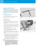
Longevity® Constrained Liner Surgical Technique Supplemental Screw Fixation Supplemental screws should be used only with a well-fixed Continuum, Trilogy IT or Allofit IT acetabular shell as the use of any constrained insert may lead to higher forces at the shell-tobone interface. Ancillary screw fixation of the shell is strongly recommended to assist in maintaining fixation at the shell-tobone interface. Screw Plug Removal If screw plugs exist in shell, remove screw plugs from holes prior to inserting supplemental screw fixation. Fig. 4 Attaching the bit to the Flex Drill with the Hex Wrench....
Open the catalog to page 4
Longevity® Constrained Liner Surgical Technique Screw Insertion (continued) • To loosen the set screw, turn it counterclockwise until the thread fully disengages from the flexible shaft. The set screw will be captured in the flexible drill shaft between the threads and the screw stop. (Fig. 6) • Alternatively, the set screw can be removed by turning it clockwise to fully disengage the set screw. Place it into the set screw holder in the instrument tray. • After either loosening or removing the set screw, remove the drill bit. After drilling the pilot or tapping the Screw hole: • Use the Depth...
Open the catalog to page 5
Longevity® Constrained Liner Surgical Technique Provisional Liner Positioning • There are two styles of Provisional Liners. One with a Locking Screw that is independent of the Provisional Liner, and one with a Locking Screw permanently affixed within the Provisional Liner. The permanently affixed locking screw provisional liners are available in a Continuum/Trilogy IT version and an Allofit IT version to accommodate the polar screw threads of each shell system. The Allofit IT permanently affixed locking screw provisionals have offset curves etched at the pole for identification purposes (Fig....
Open the catalog to page 6
Longevity® Constrained Liner Surgical Technique • Important: The Provisional Liner is a direct representation of the assembled implant liner and constraining ring. Therefore, it is extremely important to make sure that all bone and soft tissue have been cleared from the periphery of the shell in order to help facilitate the proper seating of the liner provisional as well as the final implants. This is best accomplished by either direct visualization or by palpating the entire periphery of the shell. • The aim of the trial reduction is to locate the optimal rotational position of the constraining...
Open the catalog to page 7
Longevity® Constrained Liner Surgical Technique Liner Insertion • Prior to inserting the Longevity Constrained Liner, ensure that the Shell interior is clean and dry. • Place the final polyethylene Liner into the implanted Shell by hand, or use the Liner Insertion Instrument. • Spin the Liner until scallops engage. Note: Before impaction, the polyethylene Liner will not be flush with the rim of the Shell. • Select the proper size constrained Liner Impactor Head and attach it to the Universal Handle. (Fig. 16) · Align the pins on the Universal Handle with the keyhole slot on the underside of the...
Open the catalog to page 8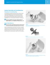
Longevity® Constrained Liner Surgical Technique Implant Assembly and Final Reduction Preparation of Constraining Ring To assemble the Longevity Constrained Liner, place the metal Constraining Ring over the head of the femoral component in the proper orientation (Fig. 18). The top-side of the ring with the two protruding fingers must point toward the femur. The underside of the ring, which will contact the face of the polyethylene liner, must be towards the patient’s acetabulum. Note: For clarification, the ring is engraved with “TOWARDS FEMUR” and “TOWARDS ACETABULUM” (Fig. 19). Femoral Head...
Open the catalog to page 9
Longevity® Constrained Liner Surgical Technique Constraining Ring Assembly to Insert • To attach the metal constraining ring to the insert, advance the ring from around the femoral neck to the face of the insert. (Fig. 21A) • To ensure proper alignment of the ring, the titanium pegs on the flat side of the reinforcement ring must fit into the slots on the outside of the polyethylene liner. • When properly positioned, the fingers of the metal ring are aligned with the fingers on the polyethylene liner. • There are two types of Ring Impactors available. The Axial Constraining Ring Impactor and...
Open the catalog to page 10
Longevity® Constrained Liner Surgical Technique The constraining ring is fully seated when the metal constraining fingers are seated either flush or slightly below the level of the polyethylene constraining fingers on the liner and is consistent on both sides of the liner (Fig. 23). This will be palpable if direct visualization is not possible. If the metal constraining fingers are not seated flush/slightly below the polyethylene on both sides (Fig. 24), check that there is no soft tissue trapped between the constraining ring and the periphery of the shell or liner and repeat the impaction with...
Open the catalog to page 11All Zimmer Biomet catalogs and technical brochures
 Oxford® Partial Kne
60 Pages
 Distal Femoral Replacement
72 Pages
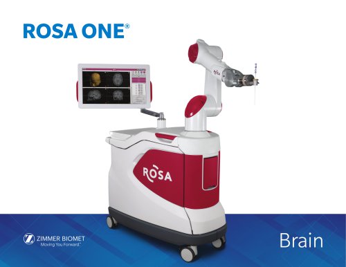 ROSA ONE® Brain System
7 Pages
Archived catalogs
 MODULAR FEMORAL Revision System
14 Pages
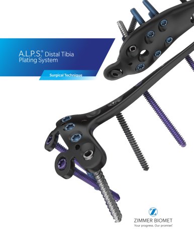 A.L.P.S.®
44 Pages
 Constrained Posterior Stabilized
12 Pages
 Persona PERSONALIZED KNEE
7 Pages
 Avenir® Femoral Hip System
12 Pages
 The CLS® Spotorno® Stem
16 Pages
 Alloclassic®Zweymüller®Stem
12 Pages
 ®Zimmer® Segmental System
6 Pages
 Zimmer Natural Nail System
8 Pages
 modern-cementing-technique
16 Pages
 CoAxial Spray Kit
8 Pages
 Biologics
24 Pages
 PowerPump DP System
2 Pages
 Sidus
Sidus40 Pages
 Ankle Fix System 4.0
8 Pages
 Anatomical Shoulder System
6 Pages
 NexGen® RH Knee
8 Pages
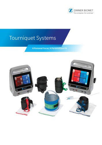
 tourniquet-systems-brochure
8 Pages
 Persona-Partial
12 Pages
 Fitmore Hip Stems
6 Pages
 NexGen High-Flex Implant
8 Pages
 Trabecular Metal ™Glenoid
4 Pages
 Anatomical Shoulder ™ System
6 Pages
 Zimmer ® PSI Shoulder
6 Pages
 Zimmer personna
12 Pages
 ZImmer iASSIST
44 Pages
 Fitmore ® Hip Stem
24 Pages
 Persona Knee
6 Pages
 Trauma Solutions
10 Pages
 Colagen Repair Patch
2 Pages
 Fitmore® Hip Stem
6 Pages
 Zimmer® Segmental System
6 Pages



- Detection kit
- ZIMMER BIOMET bone plate
- ZIMMER BIOMET compression plate
- ZIMMER BIOMET metallic compression plate
- Immunoassay detection kit
- ZIMMER BIOMET locking compression plate
- Infectious disease detection kit
- Titanium compression plate
- Surgical system
- Distal compression plate
- Cutting electrosurgical system
- Tablet computer software
- Cassette detection kit
- Chromatographic immunoassay test kit
- Coagulation surgical system
- Agitator
- ELISA detection kit
- Proximal compression plate
- Benchtop agitator
- Planning software