
- Catalogs
- Zimmer Biomet
- Zimmer® Distal Radius Plating System Surgical Technique 97-2328-002-00


Zimmer® Distal Radius Plating System Surgical Technique 97-2328-002-00

Zimmer® Distal Radius Plating System Surgical Technique 97-2328-002-00
The Zimmer® Distal Radius Plating System is designed for versatility and ease of use, accommodating a variety of anatomies and fracture patterns. It features anatomical contouring and polyaxial screw placement to minimize soft tissue interference, supported by comprehensive instrumentation.
Plate Families and Features
The system includes several plate types: Wide Volar, Dorsal, Radial Styloid, Standard Volar, Narrow Volar, and Extra Articular Plates. Key features include optimized contouring, minimal screw head prominence, and a locking mechanism allowing polyaxial screw locking with multiple attempts per hole.
Screw Features
The system offers 2.4mm Locking Screws, 2.4mm Cortical Screws, and 1.8mm Locking Pegs, all using a single drill bit and depth gauge. Locking screws and pegs can be angled up to 15 degrees or follow a fixed trajectory. Cortical screws are color-coded for easy identification.
Instrumentation
Specialized instruments include Cobra Hohmanns, Weitlaner Retractors, Polyaxial Drill Guides, and Olive Wires to enhance ease of use and fracture site exposure.
Surgical Approach
Volar Approach: The patient is positioned supine with a longitudinal incision made to expose the radius.
Dorsal Approach: The elbow is flexed, and the arm is internally rotated with a longitudinal incision made to expose the radius.
Fracture Reduction and Temporary Fixation
K-wires are used for fracture reduction and temporary fixation. Plates are positioned proximal to the Watershed line, with cortical screws or olive wires for provisional fixation.
Plate and Screw Placement
Steps include checking K-wire placement, optional distal cortical screw placement, and inserting 2.4mm locking screws distally. Proximal screws are inserted, and final checks are performed using fluoroscopy.
Implant Removal
Implants are removed using the T8 Driver Shaft and AO Type Collet Handle. A small osteotome or elevator may be needed to separate the plate from the bone.
Item Numbers
Item numbers are provided for various plates and screws, including Left and Right Narrow, Standard, and Wide Volar Plates, Radial Styloid Plates, Dorsal Radial and Ulnar Column Plates, and Extra Articular Plates.
Overview
This document details the components and instruments of the Zimmer® Distal Radius Plating System, intended for surgical procedures involving the distal radius.
Specifications
Locking Pegs: 1.8mm diameter, lengths 10mm to 30mm.
Locking Screws: 2.4mm diameter, lengths 10mm to 30mm.
Instruments
A comprehensive list of surgical instruments includes T8 Driver Shaft, AO Quick Connect, AO Collet Handle, Depth Gauge, Calibrated Drill Bits, Drill Guides, Bending Irons, Elevator, Sharp Hook, Retractors, and Reduction Clamps.
Procedures and Recommendations
The document emphasizes that the information is general and not a substitute for professional medical advice. Each patient requires individual assessment.
Limitations
The surgical technique is not approved for distribution in the United States. Users should refer to package inserts for detailed product information, including contraindications and warnings.
Catalog excerpts

Zimmer Distal Radius Plating System ® Surgical Technique
Open the catalog to page 1
Zimmer® Distal Radius Plating System Surgical Technique Introduction The Zimmer® Distal Radius Plating System is a versatile system carefully designed to meet the needs of both patients and surgeons. Using Zimmer’s anatomical database, the plate contour conforms to a broad range of patient anatomy and the screw trajectories target the most common fragment and fracture patterns, all while limiting the construct interference with soft tissues. Zimmer has designed the Distal Radius Plating System for ease of use and polyaxial screw placement. The system offers comprehensive instrumentation to ensure...
Open the catalog to page 2
Zimmer® Distal Radius Plating System Surgical Technique Zimmer Distal Radius Plating System Plate Families Dorsal and Radial Styloid Plates Wide Volar Plates Standard Volar Plates Features Plate Contour The contour was optimized using Zimmer’s proprietary ZiBRA™ Anatomical Modeling System to ensure appropriate fit for a broad patient population. Minimal Screw Head Prominence These low-profile, periarticular plates are anatomically contoured to reduce soft-tissue irritation by minimizing screw head prominence even when the screws are used off-axis. Locking Mechanism Polyaxial screw locking is...
Open the catalog to page 3
Zimmer® Distal Radius Plating System Surgical Technique Screw Features Screw Options • 2.4mm Locking Screws Ease of Use All screws have been streamlined to use one drill bit and one depth gauge, simplifying the instrumentation for ease of use. The drill bit is etched to measure for screw length, saving time and reducing the number of steps to complete the procedure. Flexibility The locking screws and pegs in this system can be angled up to 15 degrees off-center or follow a fixed-angled trajectory with a standard locking drill guide or a drill guide block. Variable Angle Trajectory Color Coded...
Open the catalog to page 4
Zimmer® Distal Radius Plating System Surgical Technique Instrumentation Simplified The set includes specialized instrumentation geared to make the use of the system easier. Comprehensive Offering Cobra Hohmanns Wider Cobra Hohmann retractors allow improved fracture site exposure and visualization. Weitlaner Retractors Retractors specific for distal radius cases; deep teeth with a wide spread to improve exposure. Polyaxial Drill Guide Simple design to target hole and place drill bit within cone of polyaxiality. Olive Wires Shorter Olive Wires to stay out of the way of the drill while temporarily...
Open the catalog to page 5
Zimmer® Distal Radius Plating System Surgical Technique Surgical Approach Volar Approach Patient Positioning Position the patient supine and place the forearm on a radiolucent hand table. (Fig. 1) Patient Positioning 1. Incision Make a longitudinal incision slightly radial to the flexor carpi radialis tendon (FCR). (Fig. 2) 2. Superficial Dissection Retract the FCR tendon toward the ulna while protecting the median nerve. Dissect through the floor of the FCR sheath, protecting the radial artery radially, exposing the pronator quadratus (PQ). (Fig. 3) 3. Deep Dissection Release the PQ radially...
Open the catalog to page 6
Zimmer® Distal Radius Plating System Surgical Technique Fracture Reduction and Temporary Fixation 1.25mm K-wires can be used to obtain and maintain accurate fracture reduction when applying the distal radius plate. Before Plating: • Reduce fracture. • Insert K-wires to hold the reduction. (Fig. 5) • If needed, K-wires can be inserted parallel to the subchondral bone to reconstruct the articular surface. (Fig. 5) • Ensure that K-wires are placed in locations which will not impede proper plate placement and fixation. Note: K-wires and drill bits are single use only. Fig. 5 Hold reduction with K-wires...
Open the catalog to page 7
Zimmer® Distal Radius Plating System Surgical Technique Step 2: Plate Position The plate should be positioned on the distal radius proximal to the Watershed line. If placed properly, 1.25mm K-wires inserted into the two distal K-wire holes will not violate the joint. (Fig. 8) Note: The two distal K-wire holes match the trajectory of their adjacent screw holes. The K-wire holes are offset slightly more distal to ensure that the nominal trajectory of the screws will not be in the joint if the K-wires show proper placement under flouroscopy. Fig. 8 Check distal K-wire placement Note: If bending...
Open the catalog to page 8
Zimmer® Distal Radius Plating System Surgical Technique Step 4: Check Distal K-wire Placement Check 1.25mm K-wire to verify that the screw trajectory will not violate the joint. (Fig. 10) Step 5: Optional Distal Cortical Screw Placement Insert 2.4mm Cortical Screws into the distal holes using the instructions in Step 3 as needed to lag the plate and bone together and/or to assist in fracture reduction. (Fig. 11) Fig. 10 Lateral view check of Distal K-wire placement Fig. 11 Optional Distal Cortical Screw placement Calibrated Drill Bit, AO, 1.8mm Diameter 00-2366-030-18 Smooth Drill Guide for use...
Open the catalog to page 9
Zimmer® Distal Radius Plating System Surgical Technique Step 6: Insert 2.4mm Locking Screws Distally Option 1: Fixed angled screw insertion without Drill Guide Block (Fig. 12a) • Thread the 1.8mm Locking Drill Guide into selected hole. • Drill with 1.8mm Drill Bit. • Measure depth. Select appropriate screw. • Insert screw using T8 Driver Shaft and AO Type Collet Handle assembly. Fig. 12a Fixed angle screw placement without Drill Guide Block Option 2: Polyaxial locking screw insertion (Fig. 12b) • Thread Polyaxial Drill Guide into selected hole. • Drill with 1.8mm Drill Bit. • Measure depth. Select...
Open the catalog to page 10
Zimmer® Distal Radius Plating System Surgical Technique Step 7: Insert Remaining Proximal Screws Repeat procedure from Step 3 or Step 6 to insert 2.4mm Cortical Screws or 2.4mm Locking Screws in desired proximal holes. (Fig. 13) Step 8: Final Check and Closure Check screw position using flouroscopy and ensure final tightening before closure. Note: To ensure screws are not in the joint, the forearm can be elevated 10 degrees in the Anterior to Posterior view and 20 degrees in the Lateral to Medial view. Fig. 13 Positioning of Volar Plate Construct Calibrated Drill Bit, AO, 1.8mm Diameter 00-2366-030-18...
Open the catalog to page 11All Zimmer Biomet catalogs and technical brochures
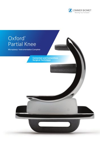 Oxford® Partial Kne
60 Pages
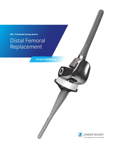 Distal Femoral Replacement
72 Pages
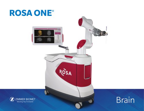 ROSA ONE® Brain System
7 Pages
Archived catalogs
 MODULAR FEMORAL Revision System
14 Pages
 A.L.P.S.®
44 Pages
 Constrained Posterior Stabilized
12 Pages
 Persona PERSONALIZED KNEE
7 Pages
 Avenir® Femoral Hip System
12 Pages
 The CLS® Spotorno® Stem
16 Pages
 Alloclassic®Zweymüller®Stem
12 Pages
 ®Zimmer® Segmental System
6 Pages
 Zimmer Natural Nail System
8 Pages
 modern-cementing-technique
16 Pages
 CoAxial Spray Kit
8 Pages
 Biologics
24 Pages
 PowerPump DP System
2 Pages
 Sidus
Sidus40 Pages
 Ankle Fix System 4.0
8 Pages
 Anatomical Shoulder System
6 Pages
 NexGen® RH Knee
8 Pages
 tourniquet-systems-brochure
8 Pages
 Persona-Partial
12 Pages
 Fitmore Hip Stems
6 Pages
 NexGen High-Flex Implant
8 Pages
 Trabecular Metal ™Glenoid
4 Pages
 Anatomical Shoulder ™ System
6 Pages
 Zimmer ® PSI Shoulder
6 Pages
 Zimmer personna
12 Pages
 ZImmer iASSIST
44 Pages
 Fitmore ® Hip Stem
24 Pages
 Persona Knee
6 Pages
 Trauma Solutions
10 Pages
 Colagen Repair Patch
2 Pages
 Fitmore® Hip Stem
6 Pages
 Zimmer® Segmental System
6 Pages



- Detection kit
- ZIMMER BIOMET bone plate
- ZIMMER BIOMET compression plate
- ZIMMER BIOMET metallic compression plate
- Immunoassay detection kit
- ZIMMER BIOMET locking compression plate
- Infectious disease detection kit
- Titanium compression plate
- Surgical system
- Distal compression plate
- Cutting electrosurgical system
- Tablet computer software
- Cassette detection kit
- Chromatographic immunoassay test kit
- Coagulation surgical system
- Agitator
- ELISA detection kit
- Proximal compression plate
- Benchtop agitator
- Planning software