- Catalogs
- Zirkonzahn
- Brochure PlaneSystem® Udo Plaster Case 2
Brochure PlaneSystem® Udo Plaster Case 2
1 /44Pages

Brochure PlaneSystem® Udo Plaster Case 2
1 /44Pages
Catalog excerpts

Analysis, acquisition and transfer of referenceable individual patient information
Open the catalog to page 1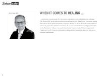
WHEN IT COMES TO HEALING … ... only the best is good enough. For this reason, we decided to work with my long-time colleague, Udo Plaster, MDT, in the realm of patient and model analysis. His PlaneSystem® is a transfer method that respects and recognises the patient as a person. Whether we choose the digital or the traditional route in the preparation of dental restorations, the accurate and individual recording of patient data by the PlaneSystem® will pave the way for the pursuit of complete health. We have integrated the PlaneSystem® ideas and improvements.
Open the catalog to page 2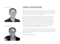
COMPLEX RESTORATION dental prosthesis. In addition to dental diagnostics, a dental technical analysis or physical diagnosis is carried out. The work steps based on this analysis also led to a high level of satisfaction and a relaxed smile for the patient whose case is presented on the following pages. The patient was provided with an implant-supported prosthesis in the edentulous mandible. In the Although the patient did not complain about functional problems, it was clearly visible that the the occlusal plane individually in order to be able to fabricate the dental restoration based on it. The...
Open the catalog to page 3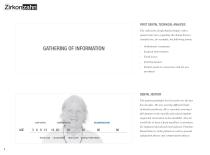
FIRST DENTAL TECHNICAL ANALYSIS The collection of information begins with a patient interview regarding the dental history; Orthodontic treatments Surgical interventions Tooth losses Existing denture Patient needs in connection with the new prosthesis DENTAL HISTORY The patient gradually lost his teeth over the last few decades. He was wearing different kinds of dental prostheses. He is currently wearing a supported restoration in the mandible. Now he ADAPTATION DENTAL PROSTHESIS Dental history of the patient as well as general adaptation phases and compensation phases.
Open the catalog to page 4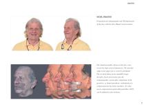
FACIAL ANALYSIS Preparation for photographs and 3D digitisation of the face with the Face Hunter facial scanner. The situation models shown on the face scan reveal the high vertical dimension. The alveolar ridge in the upper jaw is severely atrophied. The occlusal plane in the mandible drops dorsally. Each intervention into the stomatognathic system after completion of the growth (e. g. dental prosthesis, orthodontics) is compensated by the body elsewhere. For this, seven compensation points (Hergenröther, 2015)
Open the catalog to page 5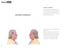
ANATOMIC LANDMARKS Landmarks (anatomic orientation points) are captured both on the face (facial landmarks) as well as on the model (cranial landmarks). ANATOMIC LANDMARKS The reference points are used as an orientation when dividing the dimensions. patient’s face. skull that can be reproduced at any time (even when the patient is edentulous). Seen from the sagittal view, these are the ala points (ala of the nose) at the right and left, the tragus (outer auditory canal) and the jaw angle.
Open the catalog to page 6
At the front, nasion and subnasal point are marked as anatomic landmarks. Division of the face into different planes. The most important point here is the stomion*. Tr N’ when articulating the “m-sound” and/or when the lips are in a relaxed position (without occlusal contact).
Open the catalog to page 7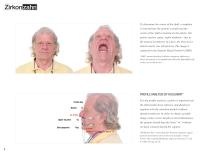
To determine the centre of the skull, a template is inserted into the patient’s mouth and the centre of the skull is marked on the palate. Ala points, nasion, spina, raphe mediana – due to the natural asymmetry of a face, the lines never match exactly (see left picture). The image is captured in the Natural Head Position* (NHP). where the patient is in equilibrium and looks himself/herself in the eyes in the mirror. PROFILE ANALYSIS BY HOLDAWAY* Profile line Nasion the Zirkonzahn.Scan software and displayed N together with the situation models (without image at the correct height (vertical dimension),...
Open the catalog to page 8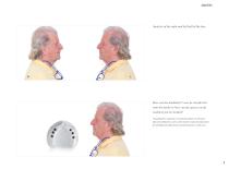
Analysis of the right and left half of the face How can the landmarks* now be transferred onto the model or how can the spaces on the toothless jaw be divided? (facial landmarks) and on the model (cranial landmarks) for dividing the dimensions (tooth position, tooth size).
Open the catalog to page 9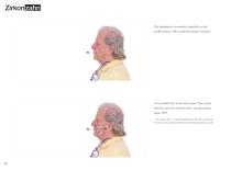
The landmarks are marked sagittally on the As a parallel line to the ala-tragus* line, a line plane (FP). * Ala-tragus line = connecting line from the ala nasi (ala of the nose) to the tragus (entrance of external auditory canal) Sto
Open the catalog to page 10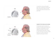
A vertical line is drawn from the marked point on the os zygomaticum to the functional plane. The intersection of this line with the Middle Zygomatic Bone ala-tragus plane indicates the position of the upper molar. DIVISION OF THE SPACES ON THE MODEL The information obtained is transferred to Middle the model. The midline and the hamulus points Zygomatic Bone (left, right) on the opalatinum are used as landmarks on the model. The previously determined position of the molars is marked dimensions as a reference point for the 23 +/- mm manufacture of the dental restoration.
Open the catalog to page 11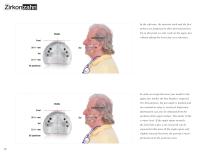
molars are displayed in their desired position. Up to this point we only work on the upper jaw Middle Zygomatic Bone without taking the lower jaw as a reference. In order to assign the lower jaw model to the upper jaw model, the bite height is required. For this purpose, the jaw angle is marked and Middle Zygomatic Bone Front 30 +/- mm 6er 23 +/- mm OS palatinum an orientation value is retrieved. Important information can also be obtained from the position of the upper molars. The molar is like a water level. If the angle opens towards the front like a fan, a lot of growth can be expected in...
Open the catalog to page 12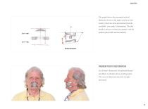
The graph shows the presumed vertical dimension between the upper and lower jaw model, which has been determined from the available “jaw angle” information. The bite height is always worked out together with the patient (physically and muscularly). Vertical dimension PREVIEW TOOTH RESTORATION For a better illustration, the planned dental prosthesis is already shown on this picture. The vertical dimension must be strongly increased.
Open the catalog to page 13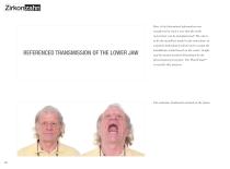
How is the determined information now transferred in such a way that the tooth restoration can be manufactured? The aim is REFERENCED TRANSMISSION OF THE LOWER JAW ®
Open the catalog to page 14All Zirkonzahn catalogs and technical brochures
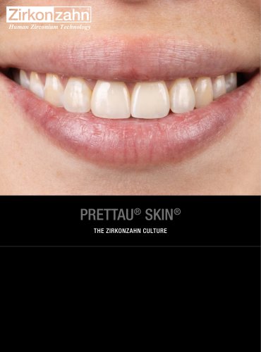
 Case gallery Prettau® Skin®
4 Pages
 Case gallery Prettau® Skin®
4 Pages
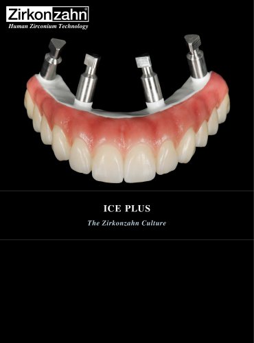 Insert ICE Plus
4 Pages
 Insert X-Ray Sphere
4 Pages
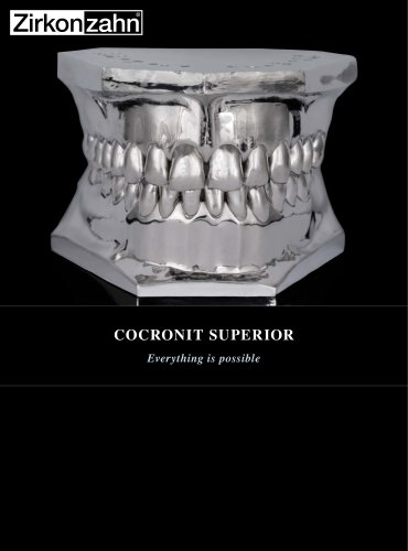 Insert Cocronit Superior
4 Pages
 Insert Clara Zanini
4 Pages
 Case gallery Prettau® Skin®
4 Pages
 Insert Zirkonofen Turbo
4 Pages
 Insert anti-snoring device
4 Pages
 Insert Gingiva-Composites
4 Pages
 Brochure Fresco Ceramics
52 Pages
 Brochure PlaneSystem®
28 Pages
 Insert Zirkonofen 600/V4
4 Pages
 Fresco Ceramics Application
6 Pages
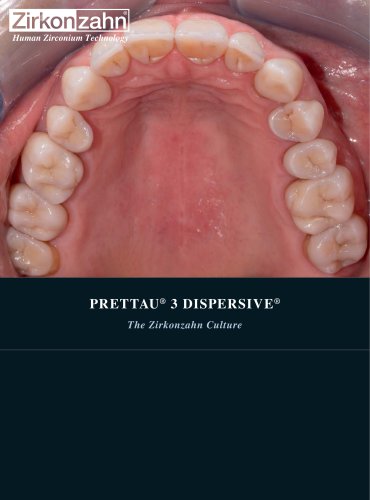 Prettau® 3 Dispersive®
4 Pages
 Brochure Detection Eye
20 Pages
 Brochure JawAligner
28 Pages
 Brochure PlaneSystem®
24 Pages
 Flyer PlaneAnalyser II
1 Page
 Flyer Head Tracker
1 Page
 Brochure CAD/CAM System
88 Pages
 Insert M6 Blank Changer
5 Pages
 Case gallery Bartplatte
4 Pages
 Brochure Zirkonzahn thinks big
12 Pages
 Brochure Shade Guide
52 Pages
 Insert Prettau® Line
4 Pages
 Case gallery Fresco Ceramics
4 Pages
 Brochure Zirkonofen Turbo
36 Pages
 Case gallery Prettau® 2
4 Pages
 Implant-supported components
100 Pages
 Case gallery Raw-Abutment®
4 Pages
 Insert Software
6 Pages
 Case gallery Bite Splint
4 Pages
 Brochure My Laboratory
32 Pages
 Brochure Zirkonzahn
68 Pages
 Brochure Military School
32 Pages
 Brochure Sintering Furnaces
28 Pages
 Brochure Patients
24 Pages
 Brochure Material diversity
116 Pages


Archived catalogs


- Zirkonzahn dental material
- Zirkonzahn dental restoration material
- Implant abutment
- Titanium implant abutment
- Straight implant abutment
- Dental surgery instrument kit
- Dental burr
- Zirkonzahn resin dental material
- Visualization software
- Internal implant abutment
- Zirkonzahn dental prosthesis dental material
- Zirkonzahn heating oven
- Modeling dental material
- Zirkonzahn dental crown material
- Zirkonzahn biocompatible dental material
- Diamond burr
- Angled implant abutment
- Dental bridge material
- Benchtop oven
- Dental laboratory dental material