
Excertos do catálogo
DISTAL FEMUR LOCKING PLATE emergency team for broken bones®
Abrir o catálogo na página 1
Properties of the material and the implant 5 Preoperative identifaction of screw length 5 Surgical Technique Time of operation & Positioning of the patient 6 Assembling of the insertion guide/extraction instrument 7 Temporarily fixation with K-Wires 10 Intraoperative identification of screw length 12 Disassembling of the insertion guide 18 Information Order information 20
Abrir o catálogo na página 2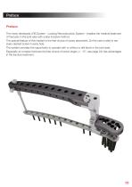
Preface Preface: The newly developed LRS System - Locking Reconstruction System - enables the medical treatment of fractures in the joint area with a less invasive method. The special feature of this implant is the free choice of screw placement. So the user is able to set every desired screw in every hole. The system provides the opportunity to operate with or without a drill block in the joint area. Especially at complex fractures the free choice of screw angle (+/- 15°, see page 24) has advantages in the fracture treatment.
Abrir o catálogo na página 3
Distal Femur Locking Plate Cancellous Screw, locking, D=5.9mm Spiral Drill, D=3.5mm, L=280mm, AO Connector Shank, PRS, Solid, WS 3.5, L=230mm, AO Connector Spiral Drill, D=3.5mm, L=280mm, AO Connector Shank, PRS, Solid, WS 3.5, L=230mm, AO Connector Spiral Drill, D=3.2mm, L=280mm, AO Connector Shank, PRS, Solid, WS 3.5, L=230mm, AO Connector Cortical Screw, locking, D=4.5mm Spiral Drill, D=3.2mm, L=280mm, AO Connector Shank, PRS, Solid, WS 3.5, L=230mm, AO Connector All I.T.S. locking plates are anatomically pre-contoured. In the unlikely event that the plate has to be formed to the bone...
Abrir o catálogo na página 4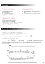
Properties Properties of the implant: Less invasive Method: • Radiolucent handle and drill block close to joint • Extraction instrument for easier reposition Multidirectional Locking Version left/right Anatomical plate design Plate lengths: 5, 9, 13-hole Plate material: Titanium Grade 2 Material of screws: TiAl6V4 ELI Easier removal of implant after fracture has healed Improved fatigue strength of implant Reduced risk of inflammation and allergy Preoperative Identifaction of screw length • • • • Preparing a x-ray with a 50mm calibration plate Measure the length of the calibration plate...
Abrir o catálogo na página 5
Indications, Contraindications Indications: For the stabilization of fractures of the distal femur • Distal shaft fractures • Supracondylar fractures • Intra-articular fractures With advanced osteoporosis In cases of skin and soft tissue problems above the lateral epicondylus Obesity Lack of patient compliance Time of operation Time of operation: • Primary: Within the first hours after trauma • Secondary: After detumescence, intermediate fixation with external fixation or extension Positioning of the patient Positioning of the patient: • Position the patient supine on a radiolucent table •...
Abrir o catálogo na página 6
Assembling of the insertion guide 1 Assembling of the clamping bolt with flat wrench, WS 11 (70011) Assembling of the extraction instrument
Abrir o catálogo na página 7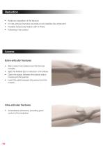
Anatomic reposition of the fracture In intra-articular fractures reconstruct and stabilize the whole joint Possible temporarily fixation with K-Wires Following x-ray control Access Extra-articular fractures • Skin incision from lateral over the femoral condyle • Split the iliotibial tract in direction of the fibres • Open the space between the lateral vastus muscle and the periost • Insert the plate between the periost and the muscle Intra-articular fractures • Anterolateral arthrotomy providing good control of the reduction
Abrir o catálogo na página 8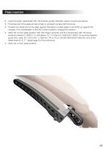
Plate insertion • Insert the plate, assembled with the insertion guide, between vastus muscle and periost • Proximal end of the plate should remain in constant contact with the bone • Position the distal end of the plate against the lateral condyle (plate must lie flat up against the condyle. If it‘s problematic to find the correct position, enlarge the incision) • Verify the correct plate position with the image converter and fix it temporarily with the tissue protection sleeve (118003-11), drill sleeve, D=1.7/3.6mm (118003-9/118003-10) and the inserted guide wire, steel, D=1.6/3.2mm,...
Abrir o catálogo na página 9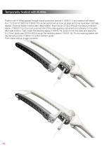
Temporarily fixation with K-Wire Fixation with K-Wires passed through tissue protection sleeves (118003-11) and inserted drill sleeve D=1.7/3.6mm (118003-9/118003-10) can be performed as soon as plate and bone have been optimally aligned. Proximal fixation follows after distal fixation. Insert trocar (57042) through the tissue protection sleeve (118003-11) in the most proximal hole of the plate (guiding instrument) and advance to the plate after stab incision. Then, insert the retaining sleeve (118003-16), screw it onto the plate and place the D=1.6mm guide wire (35164-260) through the...
Abrir o catálogo na página 10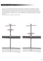
Extraction Instrument Use a D=3.2mm spiral drill (61324-280) to create a hole for the insertion of the extraction instrument (62700) through the tissue protection sleeve (118003-11) and the D=3.6mm drill sleeve (118003-10). Following removal of the drill sleeve, screw in the extraction instrument through the tissue protection sleeve into the bone. As soon as fixed in the bone, a reposition can be made by rotating the oval spindle nut while holding the T-handpiece. Turn in a screw through one of the adjacent plate holes to maintain Then, the extraction instrument can be removed.
Abrir o catálogo na página 11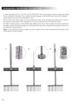
Intraoperative Identification of screw length 1. Insert the guide wire D=1.6/3.2mm (35164-260/35324-260) under image converter monitoring through the far corticalis of the plate. Then, position the depth gauge, 2 parts (59324) and read off the required screw length at the end of the calibrated K-Wire. 2. Drill screw holes under image converter guidance through the far corticalis of the plate. Then, read off the required screw length at the calibrated D=3.2/3.5mm spiral drill (61324-280/61354-280). 3. Insert the depth gauge, 2 parts (59324) after drilling screw holes. After hooking into the...
Abrir o catálogo na página 12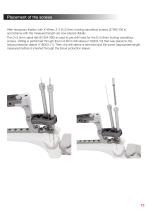
Placement of the screws After temporary fixation with K-Wires, 2-3 D=5.9mm locking cancellous screws (37592-XX) in accordance with the measured length are now placed distally. The D=3.5mm spiral drill (61354-280) is used to pre-drill holes for the D=5.9mm locking cancellous screws. Drilling is performed through the D=3.6mm drill sleeve (118003-10) that was placed in the tissue protection sleeve (118003-11). Then, the drill sleeve is removed and the screw (appropriate length measured before) is inserted through the tissue protection sleeve.
Abrir o catálogo na página 13Todos os catálogos e folhetos técnicos I.T.S.
-
 ufs
ufs1 Páginas
-
 DHL
DHL2 Páginas
-
 ITS
ITS2 Páginas
-
 DHL - Distal Humeral Locking Plates
20 Páginas
-
 PHL
PHL24 Páginas
-
 ACLS
ACLS20 Páginas
-
 CFN
CFN32 Páginas
-
 OLS
OLS24 Páginas
-
 PHLs
PHLs20 Páginas
-
 CTN - Cannulated Tibia Nail
28 Páginas
-
 UOL - Ulna Osteotomy Locking Plate
32 Páginas
-
 SR Sacral Rods
20 Páginas
-
 HCS
HCS24 Páginas
-
 TOS Twist-Off Screw
20 Páginas
-
 TLS
TLS20 Páginas
-
 PRS-RX
32 Páginas
-
 HLS
HLS20 Páginas
-
 PLS - Pilon Locking Plates System
24 Páginas
-
 ES
ES20 Páginas
-
 SR
SR20 Páginas
-
 FL
FL24 Páginas
-
 PL - Pilon Locking Plate small
12 Páginas
-
 PRS - Pelvic Reconstruction System
28 Páginas
-
 PRL - PROlock Radius Locking Plate
20 Páginas
-
 OHL - Olecranon Hook Locking Plate
24 Páginas
-
 OL - Olecranon Locking Plate
24 Páginas
-
 PHL - Proximal Humeral Locking Plate
28 Páginas
-
 CAS
CAS40 Páginas
-
 FCN
FCN20 Páginas
-
 HOL
HOL24 Páginas
-
 FLS
FLS24 Páginas
-
 PFL
PFL20 Páginas
-
 DTL
DTL24 Páginas
-
 HTO
HTO24 Páginas
-
 PTL
PTL32 Páginas
-
 DFL
DFL32 Páginas
-
 SCL
SCL32 Páginas
-
 SLS
SLS24 Páginas
-
 CAL
CAL20 Páginas
-
 DUL
DUL24 Páginas
-
 CLS
CLS28 Páginas


