
Excertos do catálogo

Implants trauma Straight Compression Locking Plate
Abrir o catálogo na página 1
CAUTION: Federal Law (USA) restricts this device to sale by or on the order of a board certified physician. WARNING: If there is no sufficient bone healing, wrong or incomplete postoperative care, plate might break. All ITS plates are preformed anatomically as a matter of principle. If adjustment of the plate to the shape of the bone is required, this is possible by carefully bending gently in one direction once. Particular care is required when bending in the region of a plate hole, as deformation of the plate may lead to a failure of the locking mechanism. The plate must not be buckled or...
Abrir o catálogo na página 2
1. Introduction P. 5 Preface P. 6 Screws P. 7 Properties P. 8 Indications & Contraindications P. 8 Time of operation 2. Surgical Technique P. 10 Drill Guide P. 10 Implantation P. 11 Compression 0 - 3.5mm P. 17 Compression 0 - 7mm P. 25 Postoperative treatment P. 25 Explantation P. 25 Summary 3. Information P. 27 Locking P. 27 Dotize® P. 28 Order list P. 29 Notes P. 30 Reconditioning Manual
Abrir o catálogo na página 3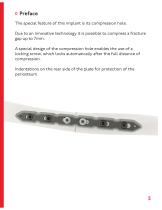
Preface The special feature of this implant is its compression hole. Due to an innovative technology it is possible to compress a fracture gap up to 7mm. A special design of the compression hole enables the use of a locking screw, which locks automatically after the full distance of compression. Indentations on the rear side of the plate for protection of the periosteum.
Abrir o catálogo na página 5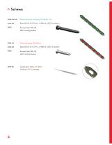
37351-XX-N-N Cortical Screw, Locking, D=3.5mm, SH 61273-100 Spiral Drill, D=2.7mm, L=l00mm, AO Connector self-holding sleeve 61273-100 Spiral Drill, D=2.7mm, L=l00mm, AO Connector self-holding sleeve 35164-150 Guide wire, steel, D=l.6mm,
Abrir o catálogo na página 6
Properties Properties of the implant: • Plate material: Titanium • Material of screws: TiAl6V4 ELI • Easier removal of the implant after the fracture has healed • Improved fatigue strength of the implant • Reduced risk of cold welding • Reduced risk of inflammation and allergy • Multi-directional locking • Indentations on the rear side of the plate for protection of the periosteum • Anatomical plate design • K-Wire holes for preliminary plate fixation • Fracture gap compression up to 7mm • Plate lengths: 4, 6, 8, 10-hole
Abrir o catálogo na página 7
Indications, Contraindications & Time of operation Indications: • The plate should primary be used to reconstruct an anatomic situation • Corrective osteotomies The plate is not intended for shaft fractures of large bones such as femur and tibia Advanced osteoporosis In cases of skin and soft tissue problems Obesity Lack of patient compliance Time of operation: • Whitin the first hours after trauma • After swelling decreases (5-10 days)
Abrir o catálogo na página 8
Surgical Technique
Abrir o catálogo na página 9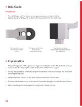
Drill Guide Properties: • Two drill holes for free choice of using compression or static fixation • Special design of drill guide enables centric placement in the plate hole Hole close to handle for drilling a fixation screw Dark grey marked hole for drilling a compression screw Asymmetric centering assistance for easy placement in the plate hole Implantation • Prepare the patient with a general or regional anesthetic to the affected limb and use a pneumatic (tourniquet) for partial deprivation of the blood supply. • During the procedure, observe (using intra-operative x-ray fluoroscopy)...
Abrir o catálogo na página 10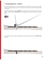
Compression 0 - 3.5mm For the compression up to 3.5mm alternatively the D=3.5mm cortical screw and the D=3.5mm locking cortical screw can be used at one side of the fracture to fixate the plate on the bone. Attach the drill guide, D=2.7mm (62216) in any plate hole. Use the spiral drill, D=2.7mm, L=100mm, AO Connector (61273-100) to drill through the hole close to handle of the drill guide. In accordance with the measured length a D=3.5mm locking cortical screw (37351-XX-N) is placed.
Abrir o catálogo na página 11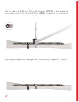
Use the spiral drill, D=2.7mm, L=100mm, AO Connector (61273-100) to drill through the hole close to handle of the drill guide, D=2.7mm (62216) in the plate hole near the fracture. In accordance with the measured length a D=3.5mm cortical screw (32351-XX) is placed.
Abrir o catálogo na página 12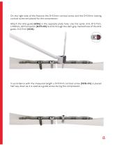
On the right side of the fracture the D=3.5mm cortical screw and the D=3.5mm locking cortical screw are placed for the compression. Attach the drill guide (62216) in the opposite plate hole. Use the spiral drill, D=2.7mm, L=100mm, AO Connector (61273-100) to drill through the dark gray marked hole of the drill guide, D=2.7mm (62216). In accordance with the measured length a D=3.5mm cortical screw (32351-XX) is placed half way down as it is used as a guide screw during the compression.
Abrir o catálogo na página 13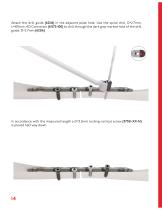
Attach the drill guide (62216) in the adjacent plate hole. Use the spiral drill, D=2.7mm, L=100mm, AO Connector (61273-100) to drill through the dark gray marked hole of the drill guide, D=2.7mm (62216). In accordance with the measured length a D=3.5mm locking cortical screw (37351-XX-N) is placed half way down.
Abrir o catálogo na página 14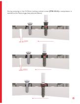
During screwing in the D=3.5mm locking cortical screw (37351-XX-N) a compression is exerted to the fracture gap (see pictures below).
Abrir o catálogo na página 15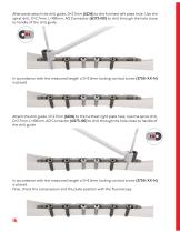
Afterwards attach the drill guide, D=2.7mm (62216) to the furthest left plate hole. Use the spiral drill, D=2.7mm, L=100mm, AO Connector (61273-100) to drill through the hole close to handle of the drill guide. In accordance with the measured length a D=3.5mm locking cortical screw (37351-XX-N) is placed. Attach the drill guide, D=2.7mm (62216) to the furthest right plate hole. Use the spiral drill, D=2.7mm, L=100mm, AO Connector (61273-100) to drill through the hole close to handle of the drill guide. In accordance with the measured length a D=3.5mm locking cortical screw (37351-XX-N) is...
Abrir o catálogo na página 16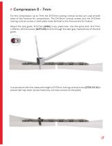
Compression 0 - 7mm For the compression up to 7mm the D=3.5mm locking cortical screws are used at both sides of the fracture for compression. The D=3.5mm cortical screws and the D=3.5mm locking cortical screws in both plate holes farthest to the fracture are for fixation. Attach the drill guide, D=2.7mm (62216) in any plate hole. Use the spiral drill, D=2.7mm, L=100mm, AO Connector (61273-100) to drill through the dark gray marked hole of the drill guide. In accordance with the measured length a D=3.5mm locking cortical screw (37351-XX-N) is placed half way down (screw head may not have...
Abrir o catálogo na página 17Todos os catálogos e folhetos técnicos I.T.S.
-
 ufs
ufs1 Páginas
-
 DHL
DHL2 Páginas
-
 ITS
ITS2 Páginas
-
 DHL - Distal Humeral Locking Plates
20 Páginas
-
 PHL
PHL24 Páginas
-
 ACLS
ACLS20 Páginas
-
 CFN
CFN32 Páginas
-
 OLS
OLS24 Páginas
-
 PHLs
PHLs20 Páginas
-
 CTN - Cannulated Tibia Nail
28 Páginas
-
 UOL - Ulna Osteotomy Locking Plate
32 Páginas
-
 SR Sacral Rods
20 Páginas
-
 HCS
HCS24 Páginas
-
 TOS Twist-Off Screw
20 Páginas
-
 TLS
TLS20 Páginas
-
 PRS-RX
32 Páginas
-
 HLS
HLS20 Páginas
-
 PLS - Pilon Locking Plates System
24 Páginas
-
 ES
ES20 Páginas
-
 SR
SR20 Páginas
-
 FL
FL24 Páginas
-
 PL - Pilon Locking Plate small
12 Páginas
-
 PRS - Pelvic Reconstruction System
28 Páginas
-
 PRL - PROlock Radius Locking Plate
20 Páginas
-
 OHL - Olecranon Hook Locking Plate
24 Páginas
-
 OL - Olecranon Locking Plate
24 Páginas
-
 PHL - Proximal Humeral Locking Plate
28 Páginas
-
 CAS
CAS40 Páginas
-
 FCN
FCN20 Páginas
-
 HOL
HOL24 Páginas
-
 FLS
FLS24 Páginas
-
 PFL
PFL20 Páginas
-
 DTL
DTL24 Páginas
-
 HTO
HTO24 Páginas
-
 PTL
PTL32 Páginas
-
 DFL
DFL32 Páginas
-
 SLS
SLS24 Páginas
-
 CAL
CAL20 Páginas
-
 DUL
DUL24 Páginas
-
 CLS
CLS28 Páginas


