
Excertos do catálogo
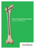
Neon Proximal Femoral Nail Surgical Technique
Abrir o catálogo na página 1
Special thanks to Contributing Surgeons, Yalkın ÇAMURCU, MD, Department of Orthopedics and Traumatology Medical Faculty of Erzincan University Erzincan, Turkey Mehmet Cenk Cankuş, MD, FEBOT Department of Orthopedics and Traumatology Medical Faculty of Sanko University Gaziantep, Turkey
Abrir o catálogo na página 2
Get Better Expertise and enthusiasm can be perfectly combined into a top-notch medical engineering company! We contribute to the development of health services by providing superior technology products at competitive costs. We envision a socially conscious business environment serving the health industry and patients get better. Dunitech branded products are designed and engineered to keep our promise; Easier Operation Better Fixation
Abrir o catálogo na página 3
TABLE OF CONTENTS Neon Proximal Femoral Nail SURGICAL TECHNIQUE NAIL REMOVAL
Abrir o catálogo na página 4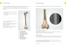
Claw Technology Dunitech leads innovational systems and aims to supply options for the surgeons to excel at their expertise. Claws Six retractable Claws are designed to penetrate the cortex and provide exceptional axial and rotational stability. are a novelty solution on distal locking systems designed to support the orthopedic trauma community. Claws are titanium pins that act as anchors to provide a stable fixation, as well as other superior operative parameters. Claws are made from titanium and mechanically deploy from within the nail. Claws penetrate through the cancellous bone and...
Abrir o catálogo na página 5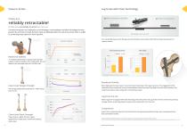
Lag Screw with Claw Technology 3x More Rotational Stability reliably retractable! All Claws were successfully retracted after every test. Conventional systems are subjected to screw breakage, screw headwear and drill bit breakage that may prevent the nail to be removed. Dunitech Claws are deployed within the nails from precise holes in a tight fit, preventing empty spaces for bone ingrowth. Virtually no cut-out Four retractable Claws anchor the lag screw into the dense cortical bone of the femoral head-neck junction for Rotational Stability superior control. Peak Compressive Forces...
Abrir o catálogo na página 6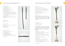
Neon Proximal Femoral Nail Specifications NEON KEY FIGURES Neon Proximal Femoral Nail Indications Intertrochanteric fractures Stable and unstable pertrochanteric fractures Distal Claws Maximum Span: 38 mm High subtrochanteric fractures without shaft extension Low subtrochanteric fractures (Neon Long Nails only) Osteoporotic fractures Fully Cannulated Body: Compatible with guide wire Pathologic/impending pathologic fractures Lag Screw Locking System: Set Screw integrated into the nail. Designed for fixed or sliding configuration while preventing rotation. Neon Proximal Femoral nails and...
Abrir o catálogo na página 7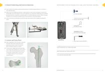
1. Patient Positioning and Fracture Reduction ● INSTRUMENTS FOR ACCESSING THE CANAL AND PROXIMAL REAMING Place the patient in the supine or lateral decubitus position according to surgeon preference on a fracture or other radiolucent table. Apply traction to the affected leg and place it in slight adduction to ease access to the greater trochanter and intramedullary canal. Alternatively, the torso can be abducted 10-15° towards the unaffected leg. The unaffected leg should be placed in a leg holder or extended away from the affected leg (Fig-1 and Fig-2). Position the image intensifier as...
Abrir o catálogo na página 9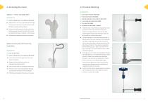
4. Proximal Reaming INSTRUMENTS: Option 1: Trocar Tip Guide Wire Neon Tissue Protector (N02-0230) Neon Entry Reamer (N02-0030) Ball Tip Guide Wire 3 mm x 900 mm (N01-0270) Trocar Tip Guide Wire 3 mm x 600 mm (N01-0250) ● 3 mm Guide Wire Sheath (N01-0280) Advance the 3 mm Trocar Tip Guide Wire through the entry point and into the proximal femur with the help of a powered driver (Fig-5). ● The wire should be centered in the canal on the and down to the bone. Secure the Neon Entry lateral view and intersect the center of the canal Reamer to a powered driver. Pass over the wire just beyond the...
Abrir o catálogo na página 10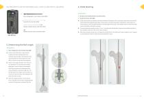
INSTRUMENTS FOR DETERMINING NAIL LENGTH AND DISTAL REAMING INSTRUMENTS: Dunitech Intramedullary Reamer Set (INST-01-002) Neon Radiographic Claw Template (N02-0080) Guide Wire Pusher (N01-0060) ● Guide Wire Pusher (N01-0060) Confirm that the fracture reduction has been maintained. Starting from 8.5 mm Reamer Cutter Head, ream until the desired depth with steady pressure (Fig-11). By each pass, increase the diameter of the Reamer Cutter Head in 0.5 mm increments. Use the Guide Wire Pusher to keep the guide wire in place. If the sheath comes out with the reamer, insert it back before starting...
Abrir o catálogo na página 11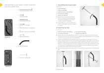
INSTRUMENTS FOR TARGET GUIDE ASSEMBLY AND NAIL INSERTION 7. Assembling the Target Guide INSTRUMENTS: Guide Arm (N02-0050) Guide Handle (N02-0060) Handle-Arm Connector Screw (N02-0200) 7 mm Hex Driver (N01-0030) Guide Arm Lock (N02-0180) Impactor (N01-0070) Mate the Guide Arm to the Guide Handle and use the 7 mm Hex Driver to tighten the HandleArm Connector Screw (Fig-13). Ensure that the connection is tight before proceeding. ● Guide Arm and engage the screw. Do not tighten at Guide Arm Lock (N02-0180) Handle-Nail Connector Screw (N02-0070) Insert the Guide Arm Lock into the bottom of the...
Abrir o catálogo na página 12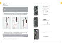
INSTRUMENTS FOR DRILLING FOR LAG SCREW INSTRUMENTS: Impactor (N01-0070) Lag Guide Pin Obturator (N02-0160) Note: 4 If the Guide Wire Sheath has not been removed, it has to be removed in before the insertion of the nail (Fig-12). 4 If a traditional ball tip guide wire was used, it must be exchanged for a smooth guide wire. The tip of traditional ball tip guide wires won’t pass through the nail. Lag Screw Guide Pin Ruler (N02-0140) ● Assemble the impactor into the Guide Handle. Pass the nail over the guide wire, through the incision and into the bone. Hold the targeting arm vertically as you...
Abrir o catálogo na página 13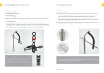
10. Preparing for Guide Pin Placement intensifier for a true lateral position. The Guide Arm should perfectly overlap the nail and femoral head, as seen in Fig-22a. If the Guide Arm is lateral to the nail and/or femoral head, reorient the nail, so they overlap. Set the nail in its final depth with the help of the image intensifier in the AP view. The projected axis of the lag screw level (Fig-22b). The minimal distance to the joint area is 5 mm. in optimal nail placement. Insert the Lag Guide Pin Obturator through the Lag Guide Sleeve and introduce the assembly through the corresponding...
Abrir o catálogo na página 14Todos os catálogos e folhetos técnicos OLIGA MAKINA ELEKTRONIK ITHALAT IHRACAT SANAYI VE TICARET LIMITED SIRKETI
-
 Navy A/R Femoral Nail
37 Páginas
-
 Nite Tibial Nail
27 Páginas